In our research project GAMMA we closely work together with MTU Friedrichshafen to optimize components of large turbochargers. Nicolas Lachenmaier, one of the leading aerodynamics engineers at MTU, uses CAESES® for the design of the turbine components. He provides a few insights into the complexity of turbine wheel design.
Interview with Nicolas Lachenmaier, MTU
FS: Hi Nicolas! What is your academic/career background, how did you find your way to MTU Friedrichshafen?
Nicolas: I’ve earned a Bachelor’s degree in Mathematics and received a Master’s degree in Computational Engineering in 2014. As my hometown lies close to Friedrichshafen, applying to MTU was a natural choice. Furthermore, I started working on turbomachinery within my Master thesis at BMW. So MTU’s offer to work as CFD engineer in the field of radial turbines matched my professional experiences and plans quite well.
FS: What are your responsibilities at MTU Friedrichshafen ?
Nicolas: MTU is developing turbocharged diesel and gas engines for off-highway applications. I am taking care of the aerodynamic design of the radial turbines within the engines’ turbochargers, i.e. I’m designing new, more efficient turbines with the help of CFD methods and evaluating experimental results from the test stand.
FS: What projects are you currently working on?
Nicolas: My main focus currently lies on the government-funded research project GAMMA. It is my task to create an automated optimization and design chain that helps creating lighter and more efficient radial turbines with high durability.
FS: What are the engineering challenges when you develop a new turbocharger turbine?
Nicolas: From the engines perspective the turbine efficiency is probably the most important design criterion. Modern CFD codes are doing a good job helping the designer to decide whether an improvement is to be expected. However, maintaining the structural integrity of the turbine wheel while continuously raising its efficiency is a tough challenge: Assuring that the stresses remain low and the eigenfrequencies high while maximizing the efficiency without increasing the inertia of the wheel can be, well, tedious.
FS: How does CAESES® support you in this task?
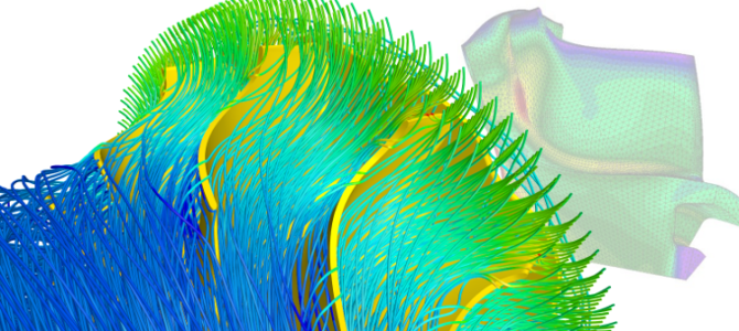
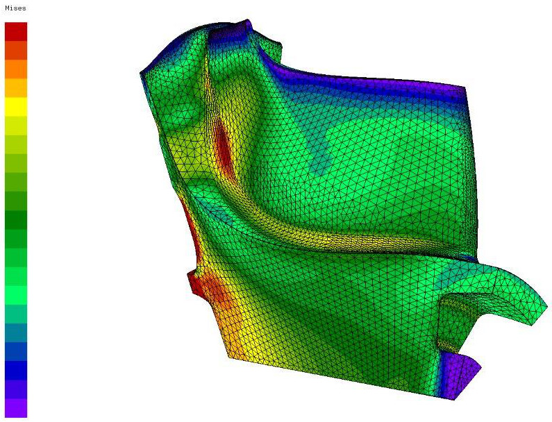
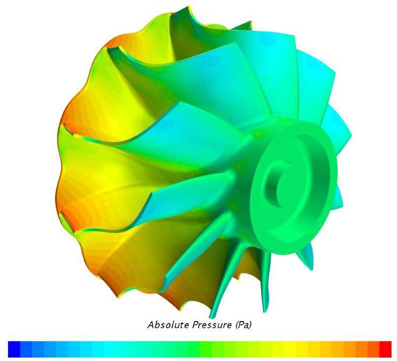
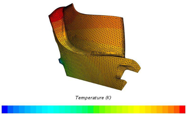
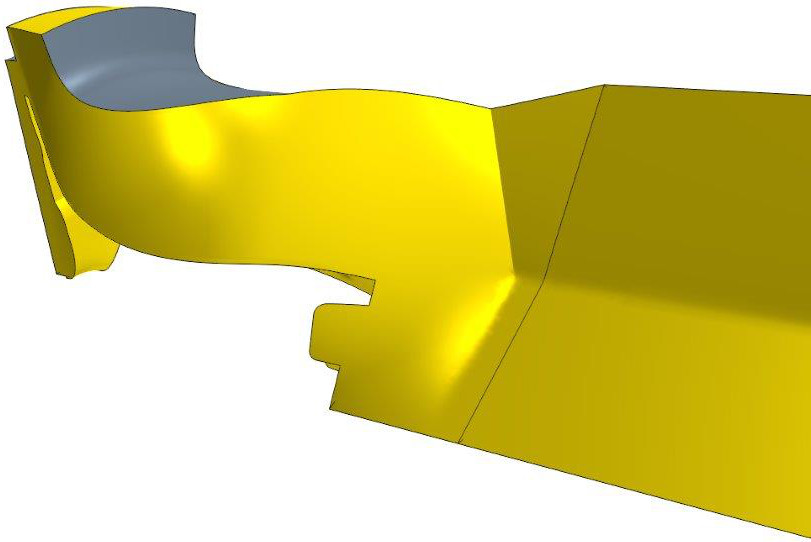
Nicolas: In close collaboration with FRIENDSHIP SYSTEMS AG we have built up a CAESES® model of a radial turbine that enables us to judge a new turbine design from several perspectives very early in the design phase: The geometry model allows us to perform CFD based aerodynamic calculations as well as all the simulations revolving around the mechanics of the geometry. We run an eigenfrequency analysis, have a closer look at the temperature and centrifugal force induced stresses and finally calculate the center of mass and inertia of the wheel.
FS: What do you like about CAESES®?
Nicolas: I enjoy how the software is specifically designed to enable and accelerate an automated geometry generation for optimization purposes.
FS: Any future ideas for the use of CAESES® in your department?
Nicolas: Well, I do hope that we’ll use the tool for the design of new water pumps in the future.
By using CAESES®, we could massively bring down our turbine design cycle from several months to only a few weeks.
— Nicolas Lachenmaier, Engineer for Fluid Dynamics and Thermal Analysis, MTU Friedrichshafen
The New Design Process at MTU
Through the use of parametric CAESES® models at MTU, a much larger set of physical quantities can now be computed automatically in a single loop. Most of the time-consuming manual iterations between the strength and aerodynamics departments in the early stage of a design are now eliminated.
The following table gives you a comparison of which quantities were available in the former turbine design process and after CAESES® was fully integrated into the workflow:
| BEFORE | AFTER | |
| Aerodynamics | ||
| Efficiency | [icon name=”check-circle” class=”2x” unprefixed_class=””] | [icon name=”check-circle” class=”2x” unprefixed_class=””] |
| Axial Thrust | [icon name=”check-circle” class=”2x” unprefixed_class=””] | |
| Rotor Dynamics | ||
| Mass of Turbine Body | [icon name=”check-circle” class=”2x” unprefixed_class=””] | |
| Axial Position of Center of Mass | [icon name=”check-circle” class=”2x” unprefixed_class=””] | |
| Transient Behaviour | ||
| Blade Intertia: Precise Calculation | [icon name=”check-circle” class=”2x” unprefixed_class=””] | [icon name=”check-circle” class=”2x” unprefixed_class=””] |
| Turbine Inertia: Precise Calculation | [icon name=”check-circle” class=”2x” unprefixed_class=””] | |
| Low Cycle Fatigue | ||
| Temperature Field | [icon name=”check-circle” class=”2x” unprefixed_class=””] | |
| Stresses due to Rotation | [icon name=”check-circle” class=”2x” unprefixed_class=””] | [icon name=”check-circle” class=”2x” unprefixed_class=””] |
| Stressed due to Transmitted Torque | [icon name=”check-circle” class=”2x” unprefixed_class=””] | |
| Stresses due to Temperature Gradients | [icon name=”check-circle” class=”2x” unprefixed_class=””] | |
| High Cycle Fatigue | ||
| Eigenfrequencies | [icon name=”check-circle” class=”2x” unprefixed_class=””] | [icon name=”check-circle” class=”2x” unprefixed_class=””] |
| Burst | ||
| Burst Speed | [icon name=”check-circle” class=”2x” unprefixed_class=””] | |
| Burst Energy | [icon name=”check-circle” class=”2x” unprefixed_class=””] |
Download Tech Brief
A short summary of this case study can be found in this tech brief (PDF).
More Information
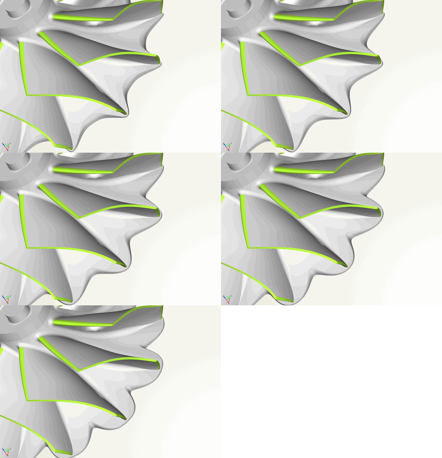
Thanks a lot to Nicolas and MTU Friedrichshafen for sharing these insights. More information about turbine wheel design including some animations can also be found in the case study Turbine Blade Optimization including Scallops. General information about turbomachinery design with CAESES® can be found in the turbomachinery section.
With kind permission of MTU Friedrichshafen
Follow Us
If you are interested in CAESES® and in CFD-driven design optimization, then sign up for our newsletter. Don’t worry, we won’t bother you with too many emails. Of course, you can unsubscribe at any time 🙂

