Turbocharger impeller design
Using CAESES, mtu Solutions implemented a fully automated, multi-objective optimization workflow for turbocharger design, integrating aerodynamics, structural, thermal, and mass analyses to deliver near-production solutions with over 50% reduced development time and engineering efficiency gains.
“By using CAESES, we could massively bring down our turbine design cycle from several months to only a few weeks.”
Nicolas Lachenmaier
Engineer for Fluid Dynamics and Thermal Analysis

About mtu
mtu Solutions, a Rolls‐Royce Power Systems brand, is a leading provider of high‐performance engines and propulsion systems for marine, power generation, industrial, and defense applications. Known for their durability, efficiency, and advanced engineering, mtu products range from diesel and gas engines to hybrid and fully electric drive systems.
With a strong focus on innovation and sustainability, mtu Solutions supports customers worldwide with cutting‐edge technology and comprehensive service solutions.
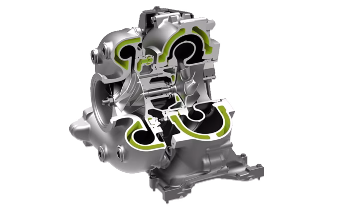
Section view of mtu turbocharger
Courtesy of Rolls-Royce Power Systems
The challenge
mtu is continuously facing the challenge of achieving sustainable power and propulsion while meeting increasing performance and regulatory demands.
A crucial engine component is the turbocharger, which must be well designed and suitably selected. Although early efforts in aerodynamic optimization of the turbocharger wheels were able to achieve significant improvements in performance measures like efficiency and pressure ratios, these designs often failed structural and service life requirements. Key factors like manufacturability, structural integrity, inertia, or eigenfrequencies were initially overlooked, and manual adjustments to meet these criteria often negated the aerodynamic gains. This revealed that focusing solely on aerodynamics was insufficient, highlighting the need for holistic, multi‐disciplinary optimization to truly enhance the turbo components. Additionally, the iterative process required to satisfy all performance, structural, and manufacturing requirements proved to be time‐consuming, significantly slowing down development and delaying the deployment of optimized solutions.
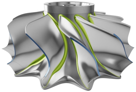
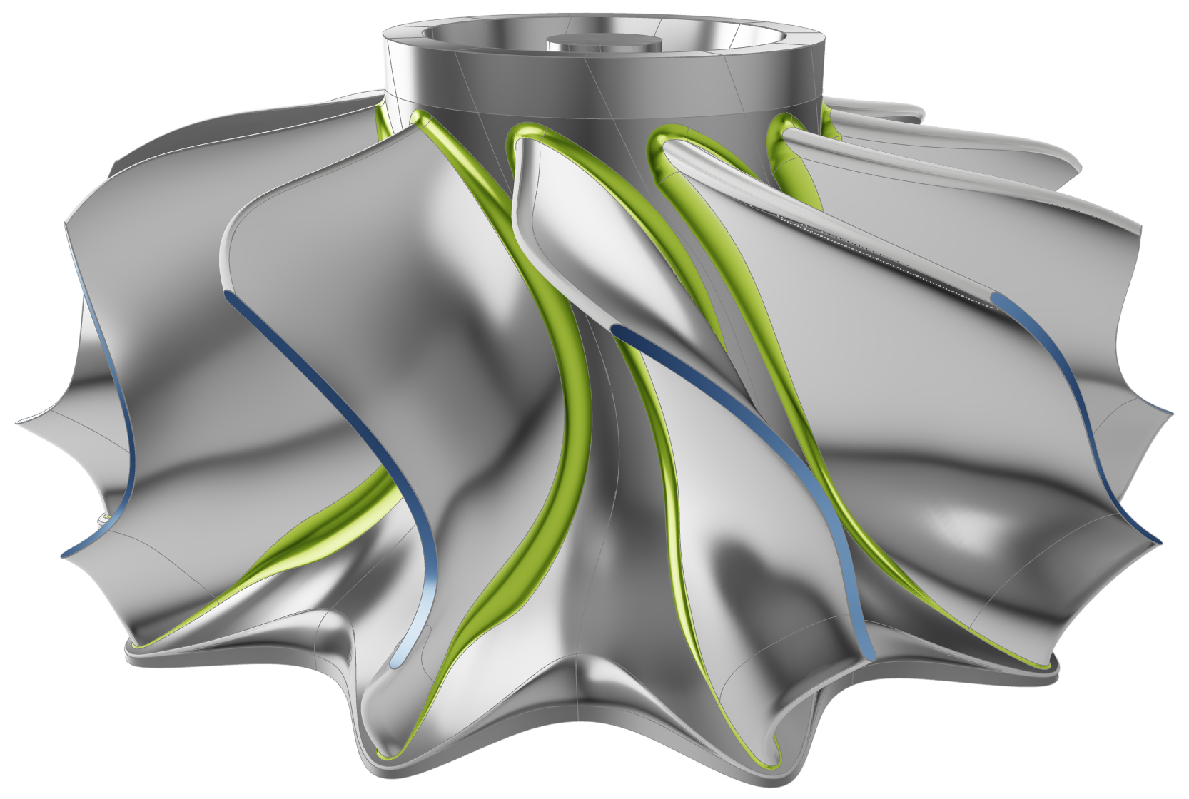
Turbine wheel modeled in CAESES
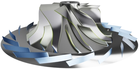
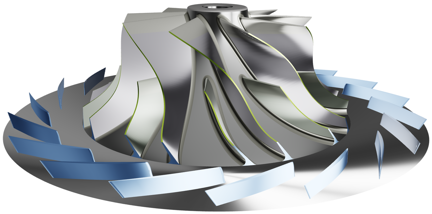
Compressor wheel modeled in CAESES
The solution
The aforementioned challenges stimulated the desire to establish and apply fully automated, multi‐objective and multi‐disciplinary optimization, developing a robust and reusable workflow that incorporated all key aspects.
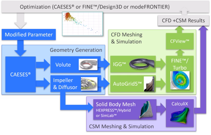
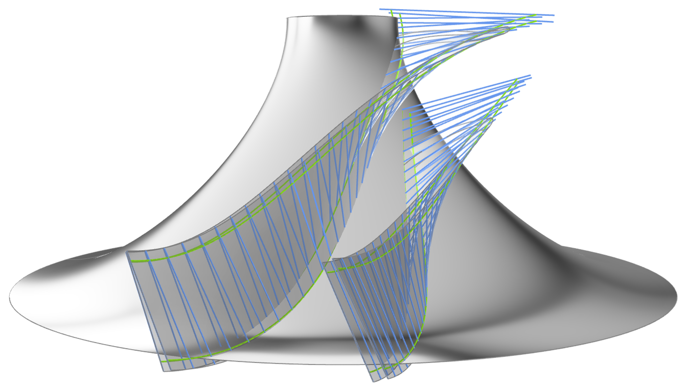
The process begins by gathering all relevant structural, aerodynamic, and design requirements, in close collaboration with the corresponding departments. It relies on a comprehensive and smart parameterization of the impeller geometries in CAESES, incorporating the following advanced features:
- Flank‐millable blade sides for the compressor and radially fibered blades for the turbine wheel.
- Scalloping and optional hub contouring of the turbine wheel to reduce weight and rotational inertia.
- Self‐adjusting fillets at blade roots to minimize mechanical strain.
- Parameterized geometry of the backdisc and shaft.
- Automated generation of simulation domains for all relevant physical disciplines.
This unified geometry model serves as the foundation for all evaluations that are executed in a fully automated way within each iteration of the design exploration or optimization process. These evaluations include:
- Aerodynamic Performance: CFD simulations for flow analysis and efficiency prediction.
- Structural Integrity: Simulations for strength assessment and vibration behavior.
- Thermal Analysis: Heat exposure simulations for the turbine wheel.
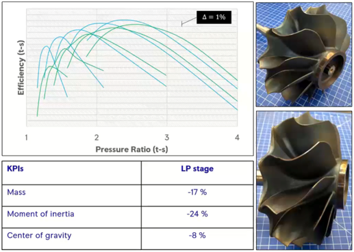
- Mass Properties: Automated determination of mass, moment of inertia, and center of gravity.
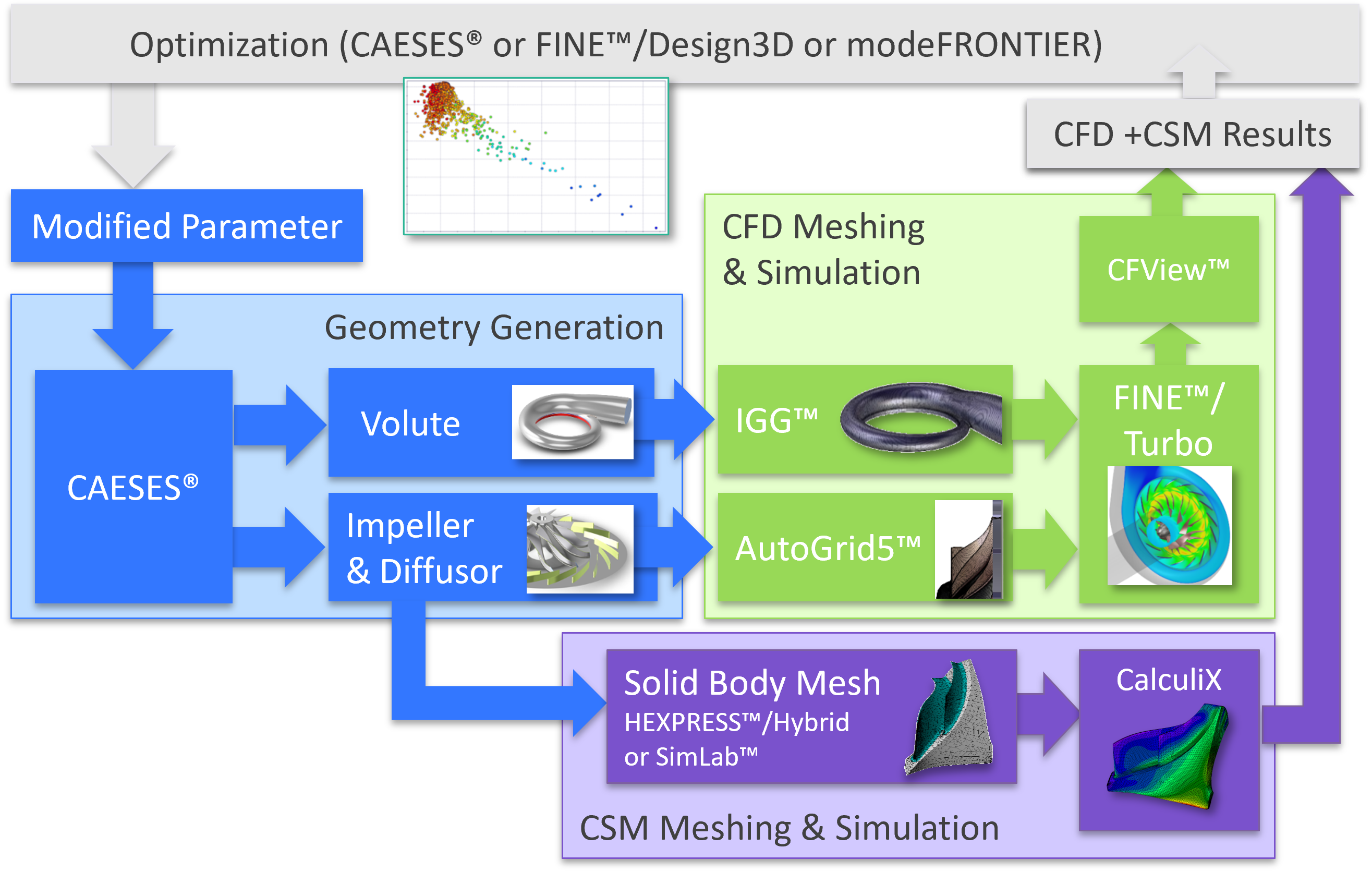
Integrated workflow for compressor optimization

Integrated workflow for turbine optimization
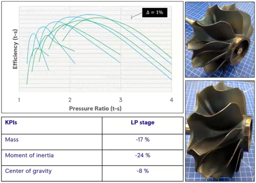
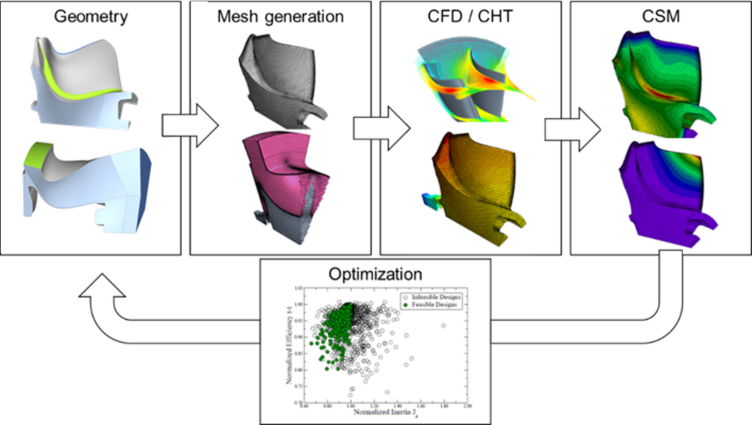
Exemplary optimization results for a mixed‐flow turbine
The benefits
This newly established process, based on CAESES, has led to significant savings in both time and resources ‐ over 50% compared to the legacy iterative approach. It delivers a design that not only achieves optimal performance, but also balances all critical requirements so effectively that it is very close to the final series production design.
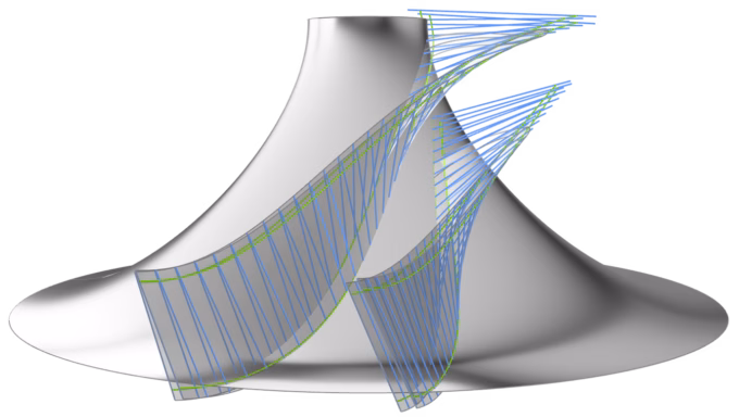
Rulings for flank‐millable main and splitter blade sides
More case studies
Turbocharger impeller design
Using CAESES, mtu Solutions implemented a fully automated, multi-objective optimization workflow for turbocharger design, integrating aerodynamics, structural, thermal, and mass analyses to deliver near-production solutions with over 50% reduced development time and engineering efficiency gains.
Compressor blade design
See how Rolls-Royce and CAESES accelerated compressor blade optimization from weeks to days, achieving smoother geometries, lower losses, and improved aerodynamic performance through advanced parametric 3D modeling.