Case studies
Explore what others create with CAESES.
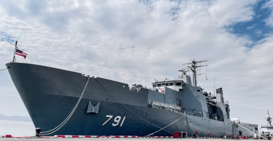
Naval ship design
TKMS leverages CAESES for naval vessel hydrodynamic design, enabling rapid hull form exploration through parametric modelling and CFD integration, balancing speed, stability, and efficiency while optimizing appendages and aftbody geometry under tight proposal-stage constraints.
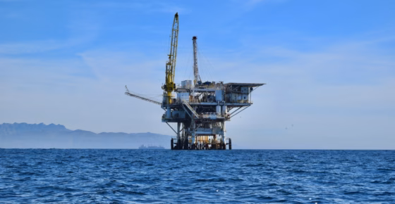
OSV design
Kongsberg Maritime uses CAESES for OSV design as a central hub, integrating hydrostatics, stability, seakeeping, DP, resistance, and cost in a multi-disciplinary workflow enabling automated optimization, improved operability, reduced CAPEX, and lower fuel consumption.
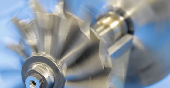
Turbocharger impeller design
Using CAESES, mtu Solutions implemented a fully automated, multi-objective optimization workflow for turbocharger design, integrating aerodynamics, structural, thermal, and mass analyses to deliver near-production solutions with over 50% reduced development time and engineering efficiency gains.
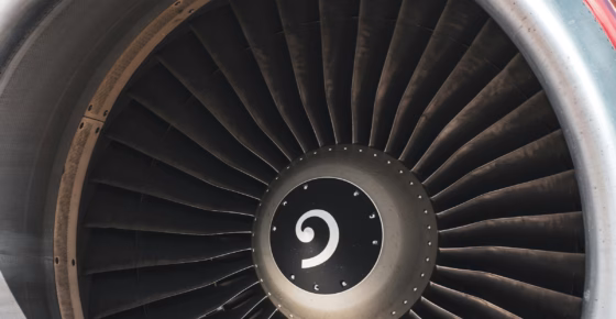
Compressor blade design
See how Rolls-Royce and CAESES accelerated compressor blade optimization from weeks to days, achieving smoother geometries, lower losses, and improved aerodynamic performance through advanced parametric 3D modeling.
Trusted by 150+ organizations in over 30 countries around the world
What our customers say

“Before introducing CAESES we ran about one hundred RANSE simulations per year. On the basis of CAESES we are now able to undertake several ten thousands of viscous simulations every year with no additional effort. This gives us an exceptional insight for key product decisions that we would not be able to generate without CAESES.”
Michael Palm
Head of Ship Hydrodynamics

“In our experience, using CAESES for creating parametric models was MUCH faster and easier than with our traditional CAD tool – hours versus weeks! For complex geometries, the traditional CAD tool was not the optimum solution because when creating variants we experienced a lot of infeasible geometries, whereas in CAESES we had almost 100% success. At Sirehna, CAESES has become an indispensable tool for conducting comprehensive shape optimization studies in an automated CFD-driven design process.”
Pol Muller
Head of Thrusters
Stay up to date
Receive latest news to your inbox.