by Yinan Bao
Heart disease is the leading cause of mortality worldwide, but with today’s advances in technology and medicine, many individuals suffering from heart disease or injury are literally getting a new lease on life. Ventricular assist devices or VADs are mechanical circulatory assist devices that help to either partially or fully replace the function of a failing heart by pumping blood from the lower chambers of the heart (ventricles) to the aorta. There are different types of VADs such as positive displacement pumps that would mimic a natural heartbeat, as well as continuous flow pumps where the recipient has no heartbeat at all! Some other differences are the type of pump – centrifugal or axial flow, the placement of the pump, and which ventricle is assisted (i.e. right – RVAD, left – LVAD, or both – BiVAD).
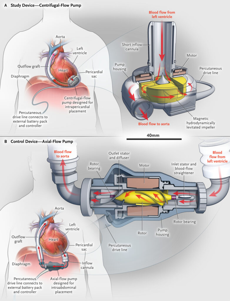
In an earlier blog post and subsequent update, we looked at a continuous centrifugal pump VAD design for right heart support (RVAD) from Penn State College of Medicine.
The present case study looks at a Left Ventricular Assist Device (LVAD) based on an axial flow pump, from the Masters’ dissertation of Yinan Bao at McGill University (Montreal, Canada), supervised by Hristo Valtchanov and Prof. Rosaire Mongrain.
A Novel Hubless LVAD Concept
An axial flow LVAD with an open hub has several advantages, firstly that it is more compact for a given flowrate and pressure, which is rather important considering that it is placed in the patient’s body. It also can be implanted percutaneously through the skin thus avoiding a more invasive surgery. A larger pumping volume, compared to the conventional axial flow pump, while operating at a slower rotational speed avoids damage to the blood cells, which is also critical.
Model Definition and Parametric Variation
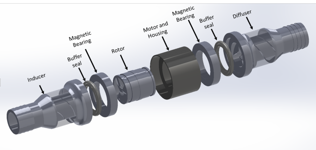
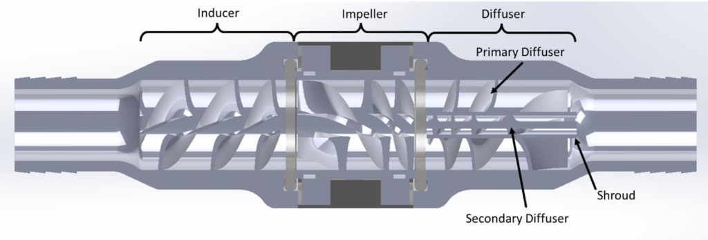
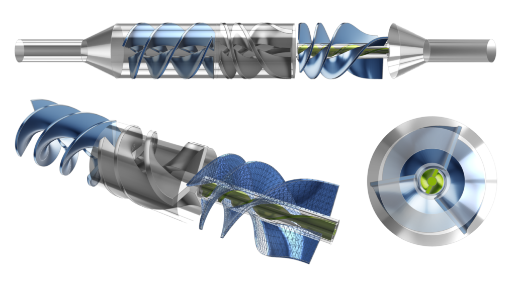
The LVAD device can be separated into various sections including: the inducer, impeller, and coaxial diffusers (primary and secondary) as shown in the figures below. All sections have helical blades (rotors or stators). The dimensions as shown are based on the initial concept for which physical testing was carried out, whereas the actual device for patients would likely be quite a bit smaller.
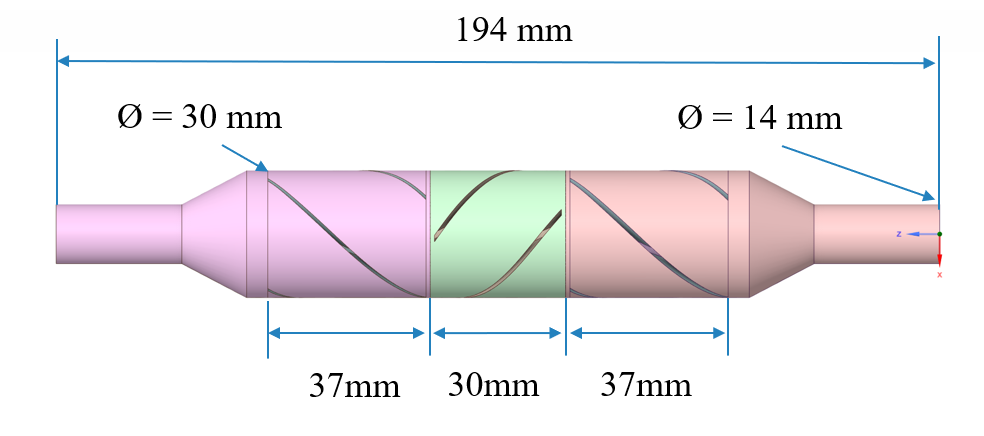
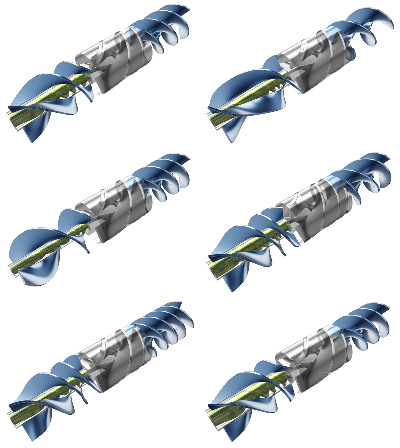
In order to explore and optimize the pump design, CFD simulations were undertaken on the flow passages of the LVAD. The model was created in CAESES® with 32 design parameters. Geometric constraints were also included in the model definition to respect the design objectives and to ensure 3D printability (constant blade thickness, minimum gap sizes, maximum overhang angles).
The following animation illustrates the variability of the model based on several of the design parameters used in the study.
Automation Workflow and Optimization Strategy
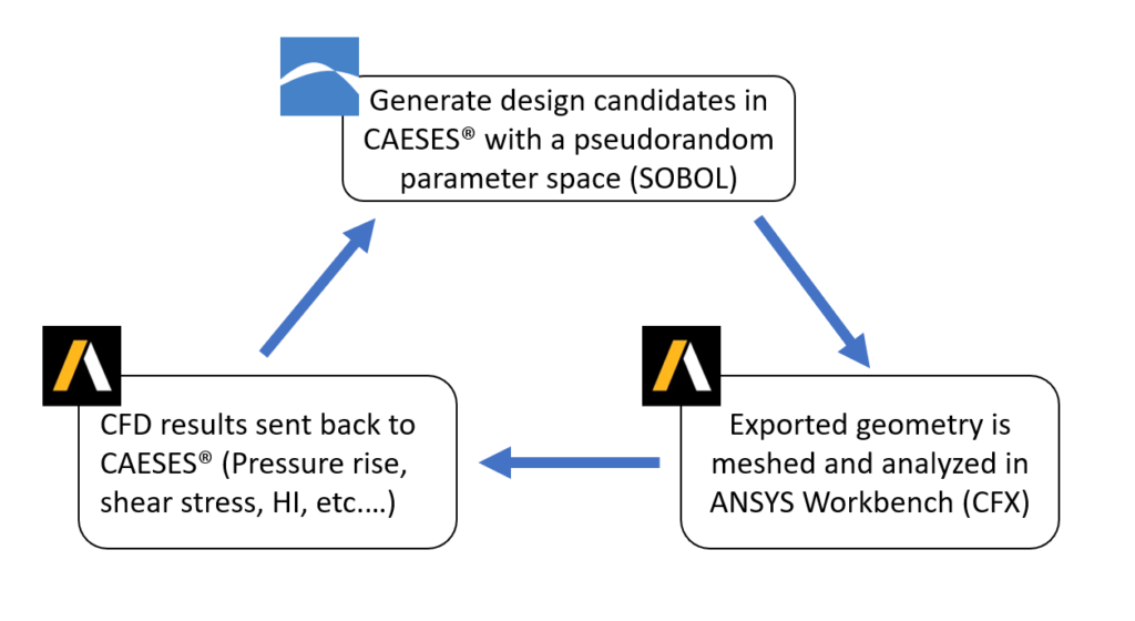
CAESES® was used as the central hub in the automation workflow. In addition to CAD generation, it was also used as the process integration and design optimization (PIDO) platform. CAESES was coupled to the Ansys Workbench in which the 3D meshing and CFD simulations took place, utilizing the CFX solver. The post-processing was also done with ANSYS.
The operating conditions for this design were 2000 RPM and 3~5 L/min.
The primary design and optimization objectives were:
- Maximize the pressure rise of the pump. Ultimately the target discharge pressure of the LVAD would be a normal diastolic pressure (70 to 80 mmHG), but by maximizing the pressure rise across the pump, the final device can be scaled down with increasing pressure.
- Minimize blood damage measured as Hemolysis Index, (HI). HI is computed using a Lagrangian approach based on a Power-law model with coefficients from Zhang and Taskin HI = C 𝜏α tβ .
Secondary objectives were to maximize pump efficiency, pressure rise through the diffuser section, and reduce swirl at the outlet.
A two-step process was employed for the optimization. In the first step, a series of design of experiments (DoE) using the Sobol algorithm were used to explore the design space and to uncover which of the parameters exhibited the highest sensitivities. The 32 design parameters were segregated into 5 groups and studied in stages. From there, a Nelder-Mead Simplex algorithm was used to run the formal optimization on a subset of design variables exhibiting the highest sensitivities.
The first group of design parameters were related to the blade angles for each section (i.e. inducer, impeller, and primary and secondary diffusers). There were 8 parameters in total representing the start and end angles; 100 simulations were run in the DoE.
The second group of design parameters were related to the blade geometry variations, including 4 parameters for blade curvature, and 4 parameters for the number of turns (where 1 turn is equivalent to 360°) of the respective sections. As with the first group, 100 simulations were conducted.
In the third group, the pump size was varied using 9 design parameters including outer casing diameter, inlet/outlet diameter, diameter ratio for inducer/impeller, as well as gap sizes at the two diffuser interfaces.
The fourth group was related to the lengths of the blades, which were varied with 3 parameters for the respective sections (inducer, impeller, diffuser).
The fifth and final group included 4 parameters representing the number of blades for inducer, impeller, and primary/secondary diffuser.
The following two tables show the normalized sensitivities of the parameters relative to pressure rise and hemolysis index, respectively. The parameters with the highest sensitivities (to one or both of pressure and HI) were then selected to form a subset of design variables to run a quicker and more efficient optimization using the Nelder-Mead Simplex algorithm. Thus, the number of parameters was reduced from 32 to the 7 exhibiting the highest sensitivities for the optimization study. (Note that outer diameter and outlet diameter were fixed.)
| Parameters | Normalized Sensitivity |
|---|---|
| Outer diameter | 1.000 |
| Diffuser number of blades | 0.936 |
| Diffuser blade length | 0.821 |
| Impeller ratio | -0.546 |
| Outlet diameter | 0.465 |
| Impeller blade length | 0.465 |
| Impeller number of blades | 0.422 |
| Diffuser turns | -0.403 |
| Impeller turns | -0.257 |
| Impeller parameter x | 0.236 |
| Inducer blade length | 0.218 |
| Secondary diffuser number of blades | 0.154 |
| Inducer number of blades | 0.144 |
| Secondary diffuser turns | 0.141 |
| Secondary ratio | -0.085 |
| Impeller start angle | -0.084 |
| Inducer gap | 0.052 |
| Impeller end angle | 0.046 |
| Inducer parameter x | 0.040 |
| Inducer ratio | -0.037 |
| Parameters | Normalized Sensitivity |
|---|---|
| Outer diameter | 1.000 |
| Impeller number of blades | 0.686 |
| Diffuser blade length | 0.559 |
| Diffuser number of blades | -0.515 |
| Inducer number of blades | 0.467 |
| Impeller parameter x | 0.211 |
| Inducer blade length | -0.210 |
| Diffuser turns | -0.205 |
| Impeller turns | -0.173 |
| Impeller ratio | -0.165 |
| Secondary parameter x | 0.161 |
| Outlet diameter | 0.134 |
| Impeller start angle | 0.116 |
| Secondary diffuser number of blades | -0.112 |
| Inducer turns | 0.102 |
| Diffuser parameter x | -0.096 |
| Inducer gap | 0.095 |
| Inducer parameter x | -0.086 |
| Secondary diffuser end angle | 0.076 |
| Secondary diffuser ratio | -0.069 |
| Impeller gap inducer | 0.064 |
| Inducer start angle | -0.061 |
| Impeller gap diffuser side | 0.061 |
| Secondary diffuser turns | -0.059 |
| Diffuser gap | 0.053 |
Results and Conclusions
In total, 500 design variants based on 32 geometric parameters were simulated over several stages using Sobol and Nelder-Mead Simplex algorithms. The optimization study resulted in significant improvements in several key parameters as shown in the following table, which compares metrics for the baseline design versus the optimized design. The design parameters with the greatest influence on delta pressure and HI, were the outer diameter of the pump (which was fixed during the Nelder-Mead Simplex), diffuser diameter ratio, and impeller ratio.
| Parameters | Baseline Design | Optimized Design |
|---|---|---|
| Pressure [mmHg] | 21.05 | 105.77 |
| HI [%] | 0.0021 | 0.0024 |
| Efficiency [%] | 7.6 | 59.6 |
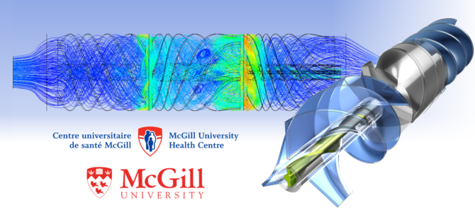
The streamlines showing the flow patterns through the VAD, as well as the pressure gradient, are compared in the following figure.
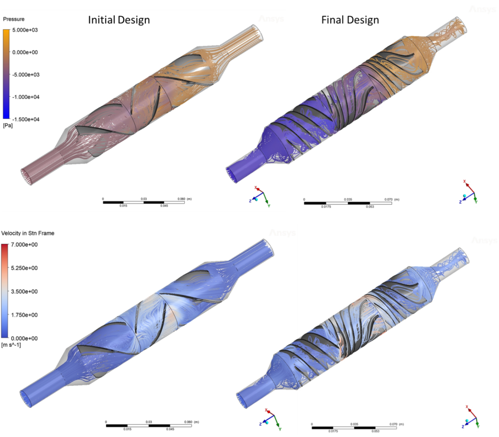
In the optimized design, there are some interesting features that facilitate the impressive increase in pressure. The blades are diverging in the z-direction, which further increases the pressure gradient by allowing the blades to act as diffusers while de-swirling the flow. This unexpected feature substantially improves pressure recovery and leads to a more compact design. Furthermore, we have a longer path length between blade channels, which allows for a more gradual de-swirling of velocity, further increasing the efficiency while reducing blood damage.
In conclusion, this case study has illustrated how CAESES®, coupled to ANSYS/Workbench was very effective at performing a design exploration and optimization of the novel LVAD concept. Furthermore, using a fully automated workflow allowed the exploration of unique design features. There were 32 parameters, of which 7 with the highest sensitivities were selected for the formal optimization, and significant improvements in pressure rise and efficiency were achieved with only modest increase to the Hemolysis index.
About the Author
Yinan Bao graduated from the University of Wisconsin-Madison having majored in Mechanical Engineering, after which he completed a research internship at Tsinghua University in China. He then went to McGill University and obtained his master’s degree in the same field. His research focus is on the optimization and CFD analysis for Left Ventricular Assist Devices (LVAD). He is implementing multiple optimization algorithms for the configuration of LVADs to reduce red blood cell damage and to increase their efficiency.
“I used CAESES as the core software for my Left Ventricular Assist Device (LVAD) optimization project. It is such a powerful optimization software that provides dozens of built-in optimization algorithms and it saved me tremendous time by automating the whole workflow.
It is also extremely user friendly and compatible with many other commercial software, which provided me more possible directions to proceed with my project. In addition, the fact that it is easy to script makes it more robust to automate any types of optimizations. Most importantly, CAESES is well documented, and it has the greatest support team. All my support tickets were thoroughly and promptly answered by the knowledgeable and patient staff.”
– Yinan Bao, MASc, McGill University, Canada
Read More
CAESES® comes with an extensive set of capabilities to support the design and optimization of medical equipment.
References:
- Yinan Bao, Hristo Valtchanov, Dr. Renzo Cecere, Prof. Rosaire Mongrain, Computational Fluid Dynamics (CFD) Analysis and Optimization of Novel Left Ventricular Assist Device (LVAD) Configuration, McGill University, 2021
- Zhang T, Taskin ME, Fang HB, et al., 2011, Study of flow- induced hemolysis using novel Couette-type blood-shearing devices. Artif. Organs;35:1180–6.
- Amy McKean, McGill Blogs, https://blogs.mcgill.ca/spellyourscience/tag/lvad

