Intake Port Design
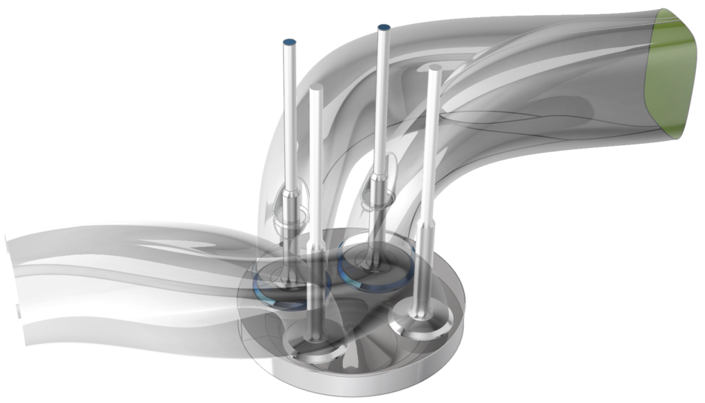
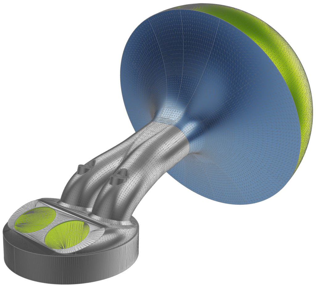
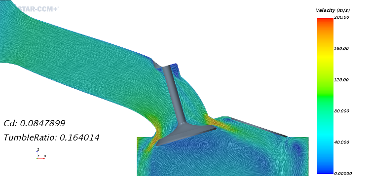
Intake ports are the final part of an engine’s air induction system. They connect the intake manifold with the combustion chamber and are opened and closed with the intake valves. While intake ports are found in all types of engines, they have an especially pronounced influence on the air/fuel mixture formation in gasoline (SI) engines. In Diesel engines, the piston bowl also helps with that task. Furthermore, the intake port shape is responsible for the charge motion, where favorably shaped vortices reduce energy dissipation, and it influences the amount of air that gets into the combustion chamber, where an increase leads to higher engine performance.
CAESES’ Intake Port Design Capabilities
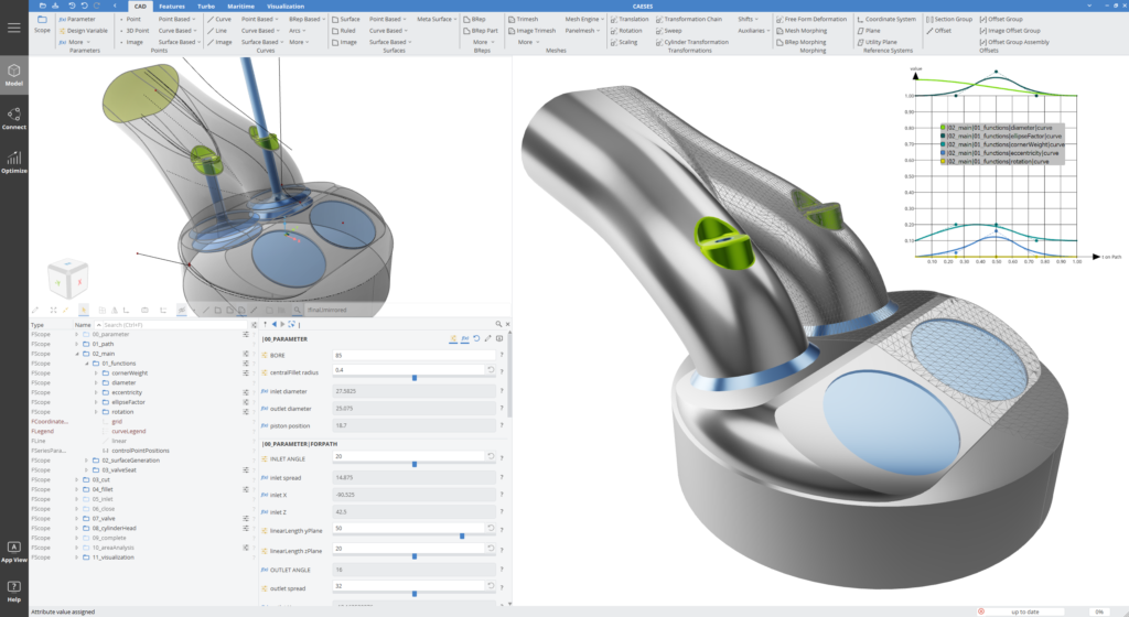
CAESES® is a dedicated CAD and automation environment for exploring and optimizing complex and performance-critical geometries (see also this overview on powertrain applications). In particular, it brings along several key capabilities for designing state-of-the-art intake ports:
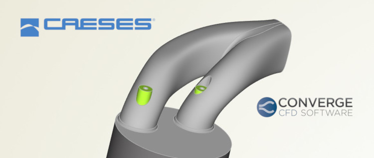
- Arbitrary types of intake ports can be modeled; symmetric, asymmetric, helical, and more.
- The geometry parameterization can be set up so that flow-relevant parameters are directly controlled, e.g., the distribution of cross-sectional area along the path, even under consideration of blocking due to the valve guide or stem.
- Alternatively, morphing methods can be used to deform an existing – imported – geometry. The morphing can be applied to a NURBS surface geometry and be exported as IGES/STEP/etc., or to a discretized geometry such as meshes or tessellations.
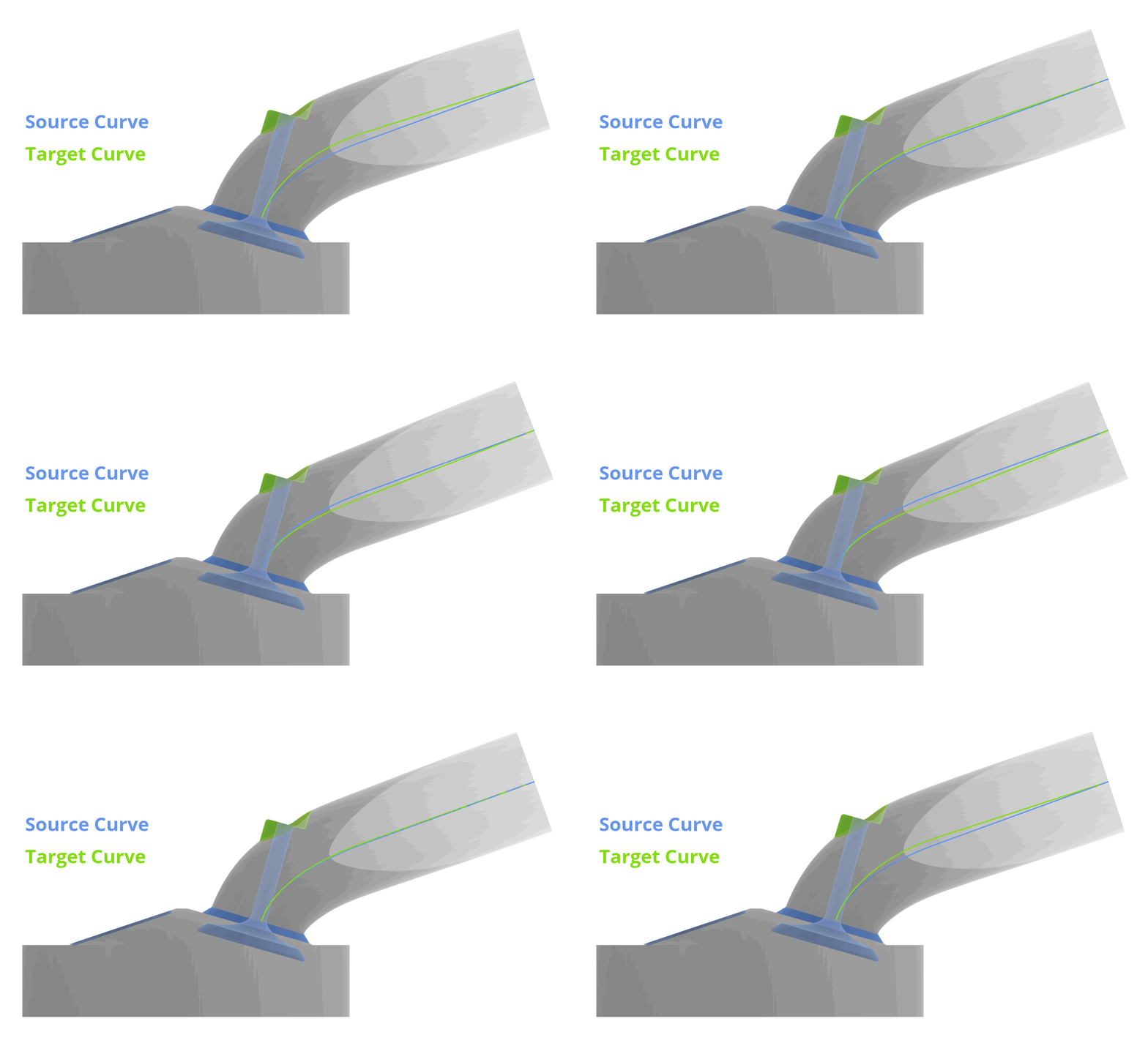
- Robust variation of the intake port geometry is possible with no failed variants. As for other geometries, one of the most important targets of our software is 100% robust geometry variation, obtained by smart parameterization and dependency-based models.
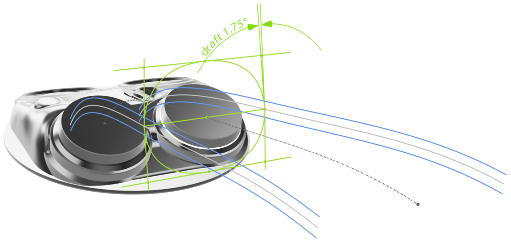
- Constraints for manufacturing can be built directly into the parameterization (e.g. drafting angles and other casting requirements).
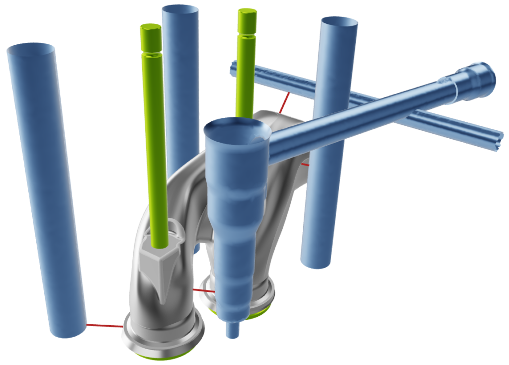
- Packaging restrictions can be considered by monitoring of minimal distances to neighboring components.
- The geometry can be exported in several different formats suitable for your CFD/meshing tools. Most of the formats support patch naming, so that the downstream tool can correctly identify surface patches for the assignment of individual mesh settings or boundary conditions.
Learn More
Intake Port Design with CAESES – Do it yourself!
1. Download CAESES®, register for a trial license, and open the intake port sample file that comes with the software.
2. Create a geometry from scratch with the intake port modeling tutorial in CAESES®.
Case Studies and Blog Posts for Intake Port Design
Questions?
Please do not hesitate to get in touch with us if you have questions in the context of your specific application. We look forward to discussing it together with you!

