How to define boundaries in CAESES for ANSYS ICEM CFD
As most of you probably know, ICEM CFD is a popular meshing software from ANSYS. It is also one of the most used meshing software when we talk about our CAESES® customer base. ICEM CFD can be perfectly integrated in highly automated processes e.g. for CFD-based shape optimizations and design studies. In our development, we had been working on the connection “CAESES® / ICEM CFD” quite a lot recently. Our target was the 100% robust data exchange with ICEM CFD in terms of keeping the assigned patch names. The thing is, if you record a meshing procedure in ICEM CFD using the replay script functionality, you have to rely on patch names. And these names need to be exactly the same whenever you load in a new design candidate. This is not always the case if you use the IGES or STEP import of ICEM CFD. So we needed another solution for our customers.
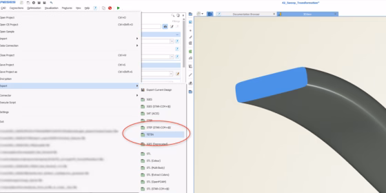
Tetin Export
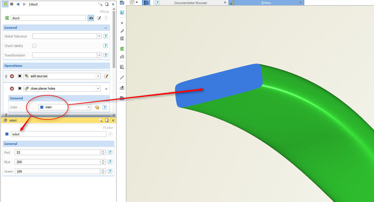
We implemented the proprietary tetin-export (*.tin) from ICEM CFD that is now also offered in CAESES®. This export makes sure that the patch names are transferred as is into ICEM CFD. But how do you assign a patch name in CAESES®? As described in previous blog posts, we use a color mechanism to do that. The user creates a new color with a custom name and assigns it to the patch. That’s it.

Create a custom color and assign it to the patch(es)
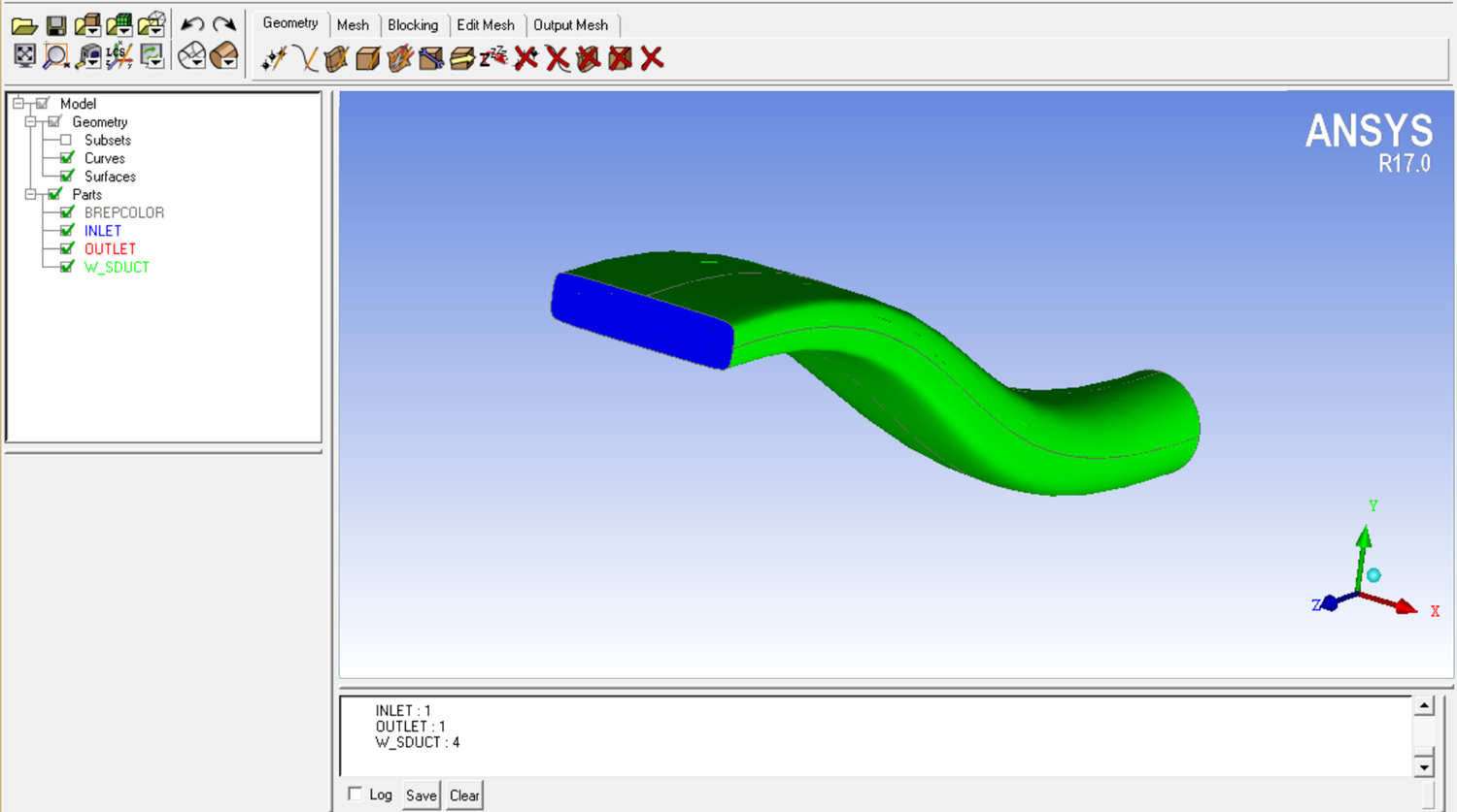
Whenever you export such a colored geometry in CAESES® using this new tetin export format, you will always receive the same “model structure” in ICEM CFD, i.e. all patch names are exactly the same again. With this, you can fully rely on what you record for a baseline design (i.e. your replay script), and the meshing procedure is automated and completely robust. Note that the assigned patch colors get transferred as well. Here is a screenshot from ICEM CFD where the duct from the previous picture was imported:

The name "inlet" is again visible in ICEM CFD
More Information
Interested in more information about CAESES®? Then check out the link below. Colored patch definitions are also available for other export formats (STL, IGES, STEP). Just drop us a line if you have further questions regarding these export topics.