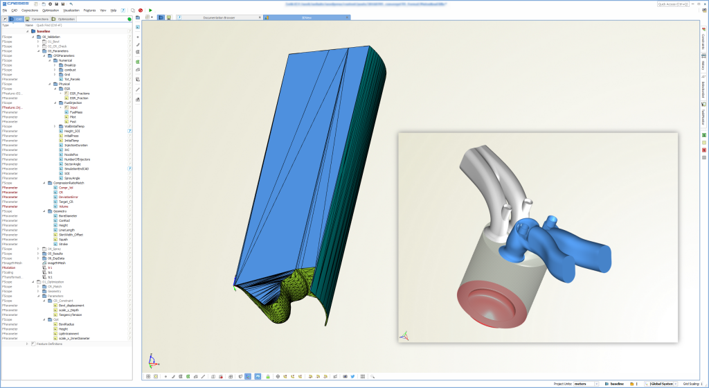
Just a few weeks ago, one of our colleagues started a comprehensive optimization of an automotive engine component with CAESES®. More detailed, he had been investigating a piston bowl design. For the CFD analysis he used the simulation software CONVERGE from Convergent Science. As usual, he integrated the CFD software into CAESES® for automation of the simulation task. Here is a screenshot of the geometry model and the corresponding periodic control volume for the CFD (click on the images to enlarge them):
The entire optimization process was robust and very effective, and the design could be improved quite a bit (watch out for the upcoming case study on our website). However, when we looked into the details of his workflow, we discovered that – for the geometry data exchange of the periodic control volume – he integrated a separate program as a workaround to convert the geometry from CAESES® into the proprietary CONVERGE format. Since the format itself is rather simple we decided to readily offer this export type to our users in the next release. The following sections describe how this new export functionality works in CAESES®.
Geometry Export
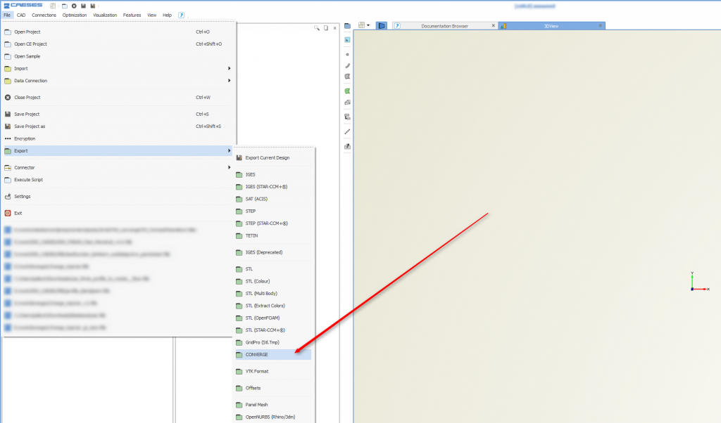
The CONVERGE geometry format is basically an ASCII file with tessellation information, including some kind of grouping mechanism, to distinguish different parts of the geometry. This new format can now be accessed through the file menu of CAESES®:
Input to this export type are tessellated surfaces i.e. triangle data. In CAESES® this means you can export any surface, as well as user-controlled triangle data, so-called trimeshes and breps with settings for the tessellation. However, you can also consider boundary information – which is the interesting part now:
Assigning Boundary Information
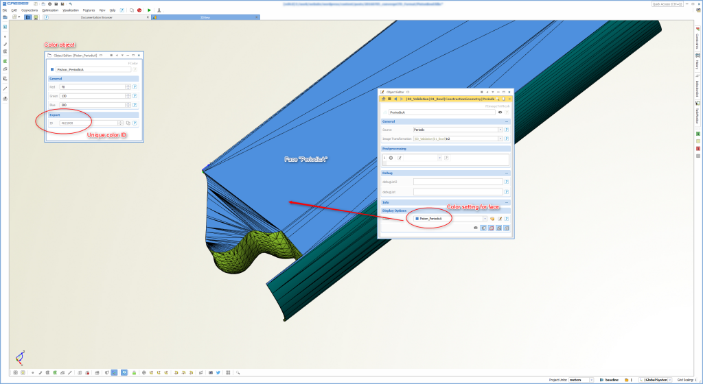
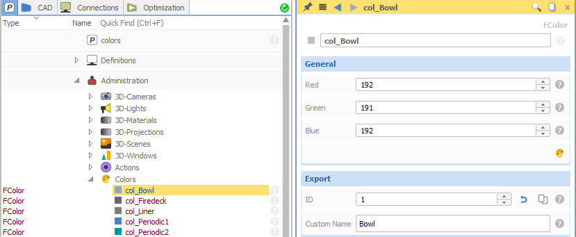
For the simulation setup in CONVERGE, it is important to know which surface patches belong to which boundary. CAESES® has an intuitive way to assign boundary “information” by means of a user-defined color. This mechanism is also used for other export types (STL, IGES, STEP – in these cases, the color name is taken for grouping). However, for the CONVERGE format, we now added unique IDs to all our colors which are automatically written into the geometry file (for the grouping). We need such an ID because names are not supported by this format. As a result, our users can export the geometry data plus the corresponding boundary information.
This is the procedure: The user creates a new color and assigns a name to it (e.g. “inlet” or “periodicwall” etc.). Such a color automatically gets a unique ID, generated by CAESES®. When using the new CONVERGE export, the IDs are transferred into the geometry output file as group IDs, and hence the grouping is directly transferred to CONVERGE.The benefit of this mechanism is that during automated design studies and optimizations the IDs do not change, and the boundaries can be referenced in CONVERGE and in all CONVERGE-related input files.
The following screenshot shows the situation in CONVERGE Studio after importing the geometry file from CAESES®. The boundary with the name “PeriodicA” (this was the color name in CAESES®) is directly shown in CONVERGE Studio and assigned to the corresponding patch.
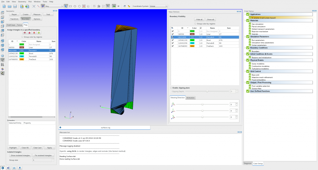
Image 4: Without any interaction in CONVERGE Studio, the boundary information was correctly set up in CAESES
Note that this setup was completely created from within CAESES®, so there was no manual interaction in the user interface of CONVERGE Studio! Exactly what we need to run automated design studies … 🙂
Simulation Setup
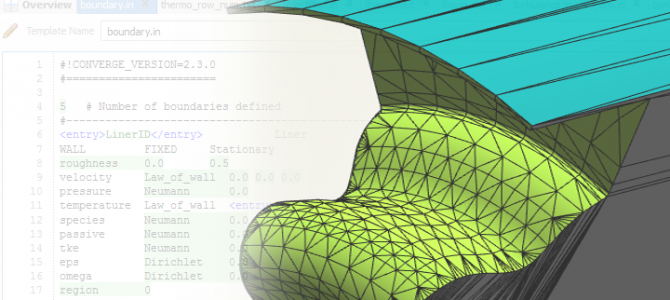
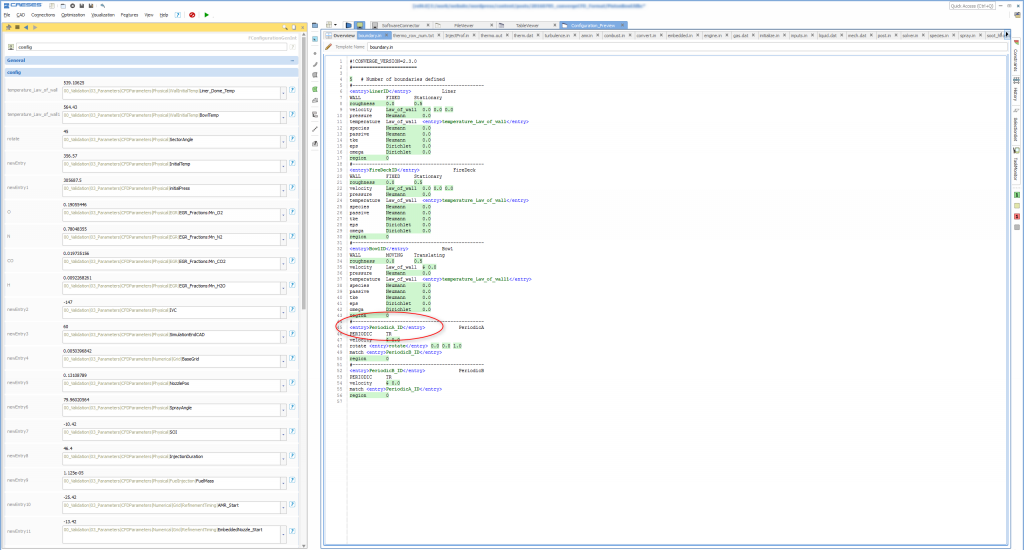
Hang on, this is not the whole story! There is some more added value to this new coloring and CONVERGE export mechanism. As already briefly mentioned, users can now also use this ID in other setup files for CONVERGE. In the next screenshot, the software connection in CAESES® is shown where the IDs are used by means of a template placeholder in a CONVERGE simulation setup file. In the automated process such as an optimization, CAESES® writes this file and includes the current color IDs of the geometry objects.
Even if the user changes the color of the geometry part, the correct ID will be automatically written into all files due to the expression mechanism in CAESES® and the dynamic placeholders of the CAESES® software connector. BTW: Note that not only the color IDs are dynamic input to this file, but any other simulation control such as the temperature, as an example.
Image 4 actually shows the situation after importing the geometry file and the simulation setup file from image 5. The widget on the right-hand side indicates that everything works well, without any error messages or warnings. Once again, the whole setup was created before in CAESES® without the need to open CONVERGE Studio at all.
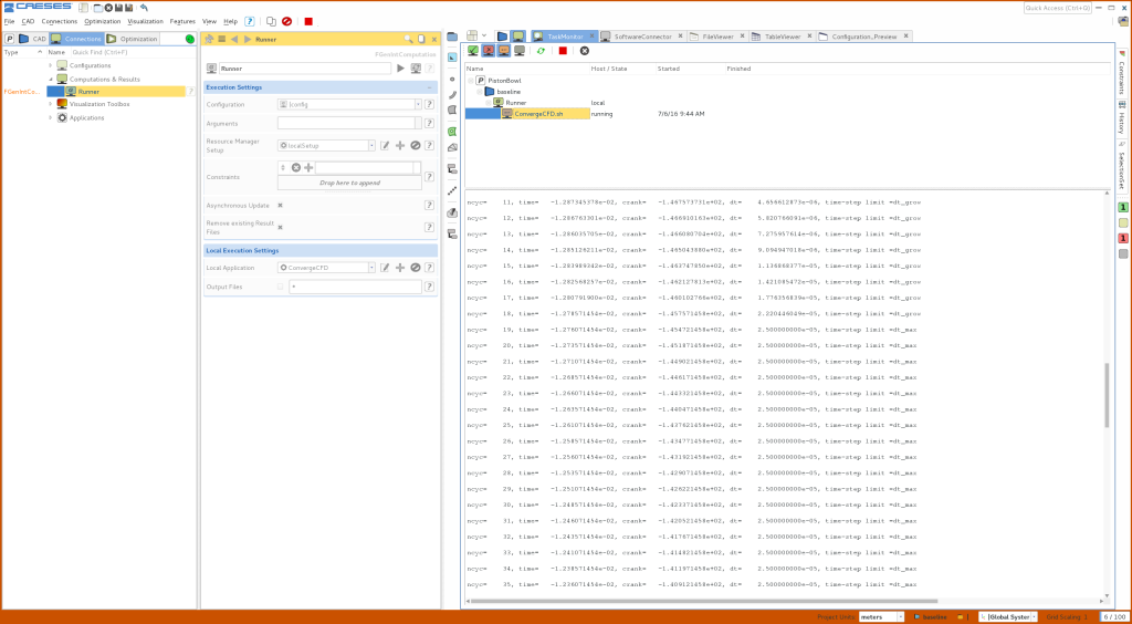
In order to close this blog post, check out a final screenshot which shows how it looks in the CAESES® user interface when you run CONVERGE for a design candidate. The task viewer on the right-hand side gives you status updates of the running CONVERGE computation, which is basically a batch mode run of CONVERGE in the background.
More Information
We hope that our “CAESES®-CONVERGE” users will like this tight data exchange, which makes it super easy now to combine these tools in automated design processes. The new export is available in versions > 4.1.2. In newer versions there is the possibility to set custom names and custom IDs, to make things even more user-friendly!
Subscribe Newsletter
Sign up for our newsletter for CAESES-related news!

Pingback: CONVERGE CFD Software: Full Automation with CAESES › CAESES