Video Blade Design Tutorial

With CAESES® 4.0, there is a lot of new and cool stuff for turbomachinery blade design. This post will give you a brief introduction into the fully-parametric design of an impeller blade, as you can typically find them in turbochargers and pumps. We have added some complementing information right below the tutorial video since not everything is covered in all details (we didn’t want to blow it up it up to a blockbuster length…).
Prerequisites
Here comes a recommendation for a higher fun factor: If you are seriously interested in setting up your own blade model in CAESES®, then check out the meta surface and feature definition tutorials (PDF) that are shipped with CAESES®. There are also several videos that complement these tutorials, e.g. the one for features and a basic volute design which illustrates the general meta surface concept.
Some of the features that are used in the video will be released with version 4.0.3. Anyway, there you go — we hope it will help you to get started with blade design in CAESES®:
Meridional Contours
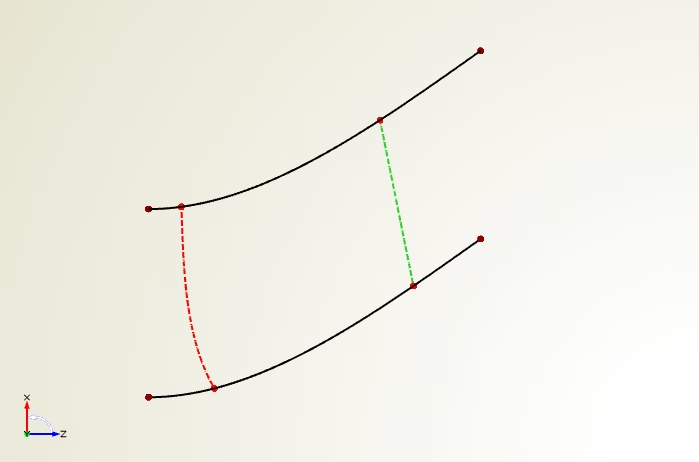
Alright, let’s get started with some comments. First of all, we create the 2D hub and shroud contours in the y‑plane of CAESES®. There is a new button for this blade view so that you can switch back at any point in time. The leading edge and trailing edge guide curves are simple connections of hub and shroud curve positions. The trailing edge guide will be used to cut off the blade in the end. In our video example, we use a smooth fspline curve where you can set start and end tangent angle. This is nice and easy to use for design studies later on. One little detail: selecting a curve and then creating a point immediately creates the point on the selected curve and you can move it along the curve by using the created curve domain parameter.
Camber Surface
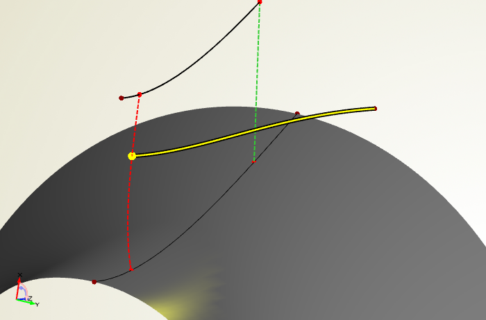
Basically, you can use any kind of camber definition in order to create a camber surface. This camber surface will be the input for applying thickness in the next step. CAESES® comes with a handy camber definition that you can directly use without any deeper knowledge. CAESES® offers the possibility to define camber data in the (m’,beta) or (m’,theta) system. If you set up 2D curves for this, then simply do it in the global xy-system of CAESES®. It gets automatically interpreted the correct way later on, i.e. beta/theta, by choosing the system at the stream section. The stream section is the curve that takes all the input (hub and shroud information, leading and trailing edge as well as camber data plus a radius location) and creates a curve in the 3D space — our 3D camber curve. BTW: the stream section is also used in the context of blade design for axial turbines and compressors.
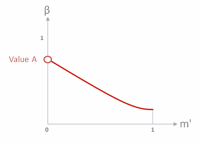
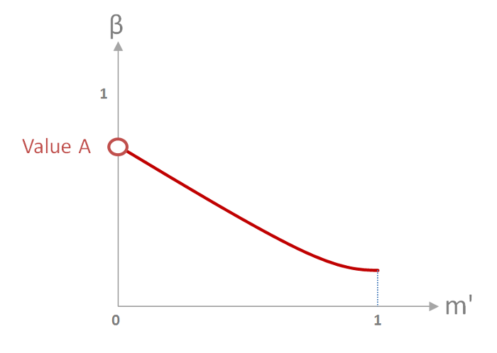
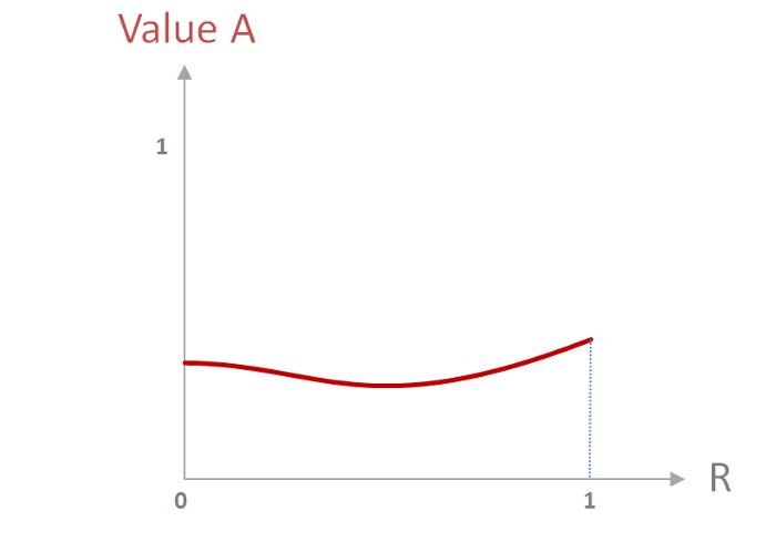
So back to our 2D camber information. In the video, the camber value at the leading edge “Value A” (or also called “Value at Start”) can be changed for a single section. In the first run, this value is kept constant in radial direction, e.g. 0.3 which corresponds to 30 degrees. Note that we always use normalized representations (easier to visualize!) and we scale it up at a later stage by using factors. The picture below shows camber data for 1 section:
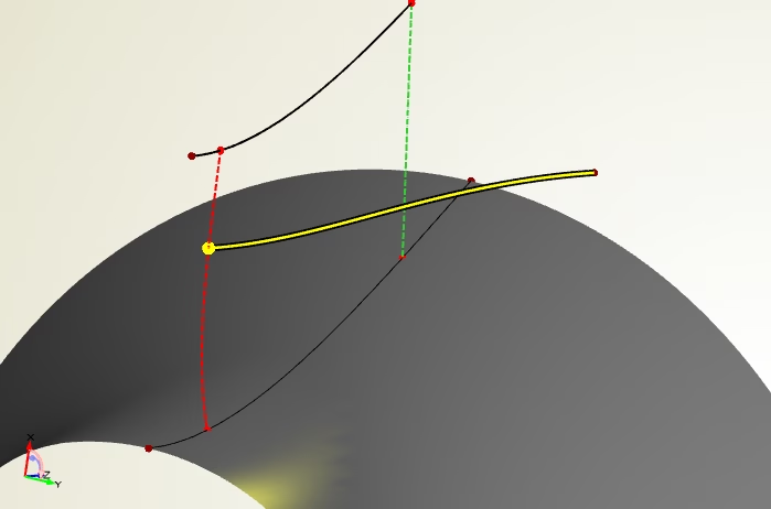
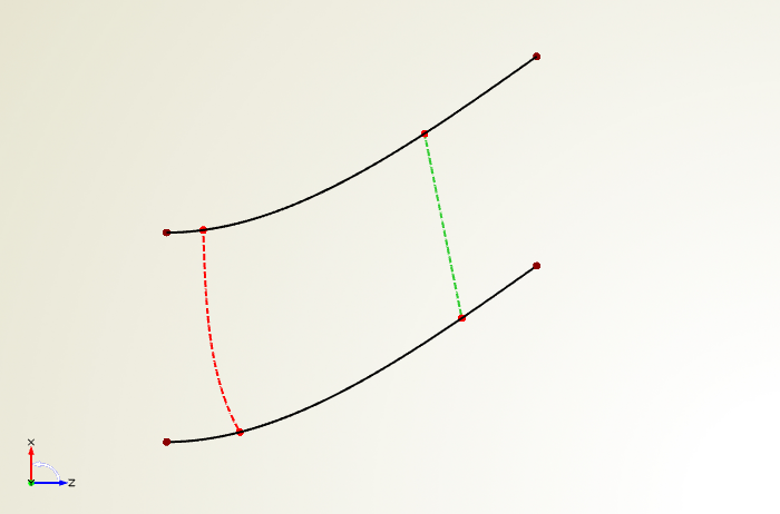
The next picture shows a stream section curve that gets generated from such camber data:
Now, we want to create a surface. The section parameter “Value A” is then controlled in radial direction by a smart function graph — yep, this is the fun part of CAESES®: Introduce graphs for any section parameter. Again, the graph is quickly created in the xy-system of CAESES®:

You can use any kind of curve type to create such a graph. It is modeled in the xy-system but gets interpreted later on as shown in the picture above (in this case: x=R=radius range, y=value A). Simply set such a graph at the curve engine instead of using the constant value. Hold on, curve engine? The curve engine object in CAESES® links together the stream section and all the user function graphs. This is basically all we need to smoothly sweep in radial direction, which is great team work of the curve engine and the meta surface:
Applying Thickness
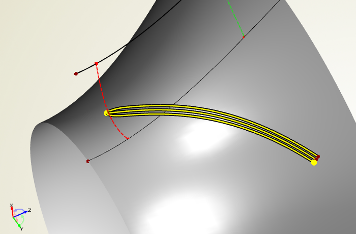
CAESES® uses a so-called offset curve to apply thickness to the camber surface. Of course, we want to control the thickness characteristics at the leading and trailing edge in radial direction. Hence, we have a user-defined 3D curve that gets controlled by function graphs. The job of creating a surface is again done by a curve engine plus a meta surface. Here is the single 3D curve that is used for our intelligent graph-based sweep:

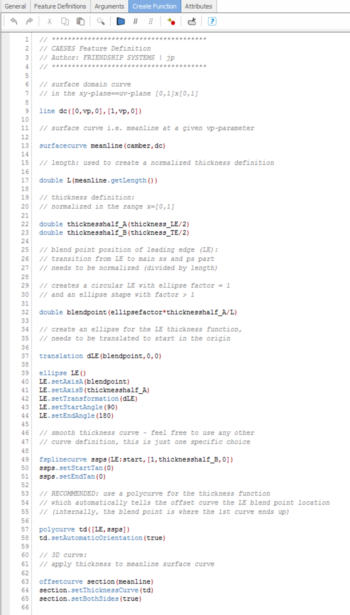
The shape of the leading edge can be controlled in the same way, i.e. we can have a circular or a more ellipse-like shape, there is a simple “ellipse factor” for this purpose. The thickness distribution and the 3D curve generation are wrapped in a feature definition so that users are able to still customize and manipulate it. In our example, we run along the camber surface, create a surface curve and apply thickness in normal direction. Let’s take a quick look into it:
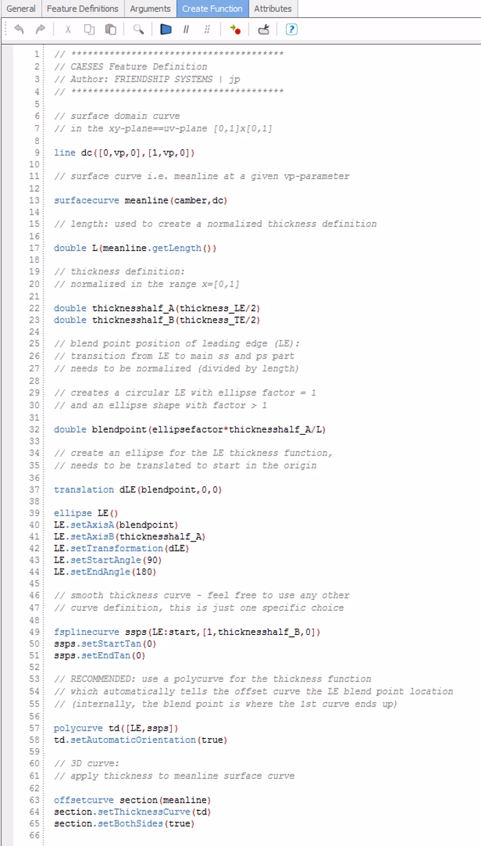
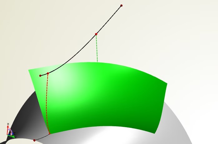
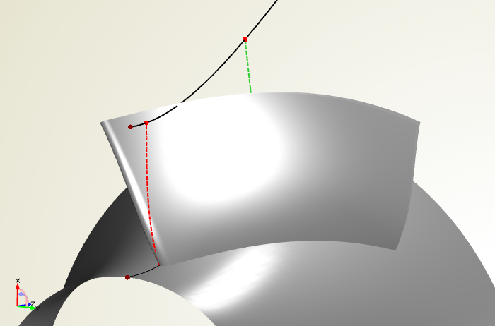
This thickness definition is shipped with CAESES® and can be readily used, e.g. as a reference for own designs. We think it is quite nice already: a smooth thickness distribution where its values, tangent angles and the ellipse factor can be controlled in radial direction. What else do you need? Finally, here comes the parametric blade surface:

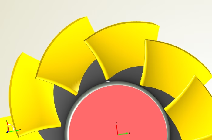
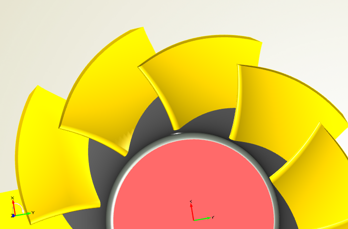
Solid Impeller
As a last step, we create the periodic blade surfaces and a solid body. For this purpose, we have prepared another fancy feature that can be readily used with just a single-click, and which is also shown in the video. The feature takes the blade, hub and shroud information plus the trailing edge guide, and then uses so-called “BReps” internally. These BReps are able to perform Boolean Operations and trimming. If needed, this feature could also generate hub and blade fillets.
Interested in trying out CAESES® for your application? Then download and install our free version today! It is fully free for commercial work, and you can directly start setting up your own intelligent model :-)