Parametric Impeller Design
The blade design capabilities of CAESES® have been completely reviewed with version 4.0, and a lot of great features have been added for the design and optimization of rotating machinery (pumps, turbochargers, turbines etc.). CAESES® is able to create any type of blade (radial, axial, mixed), and any type of 2D profile definition can be mapped into a smart parametric description. This means that CAESES® is not a black box tool that is limited to a specific blade model — of course, not! With CAESES® — plus your company-specific know-how and experience — everything is in place to develop the best blade designs in the market!
Also check out tutorial video for setting up a model from scratch:
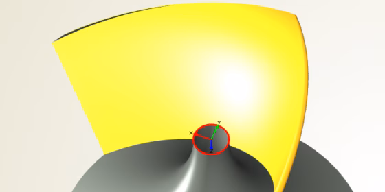
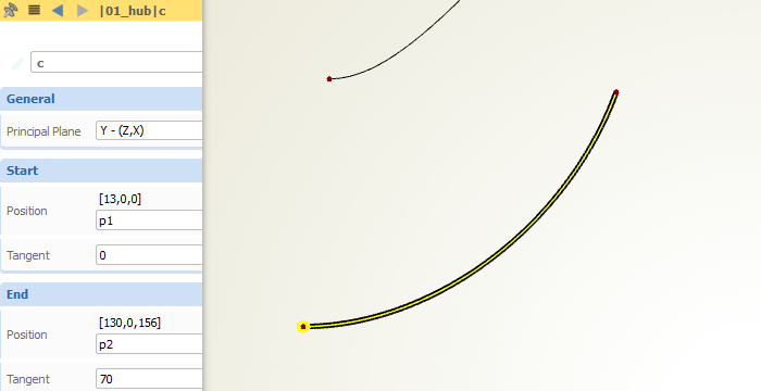
Meridional Hub and Shroud
Use all the different curve types in CAESES® to design your hub and shroud contours. Create smooth and variable shapes with our set of specialized curve types.

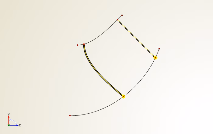
Leading and Trailing Edge
Design 2D guides for leading edge and trailing edge in a smarter parametric way. Reduce degrees of freedom — and hence the number of variables — while still maintaining most important blade characteristics.
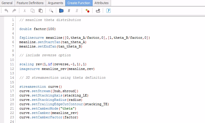
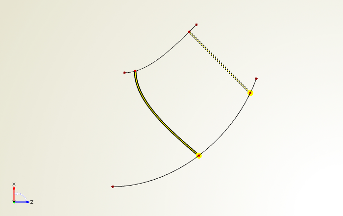
Mean Camber
Use the powerful scripting environment of CAESES® to fully customize your mean camber definition. Choose between (m’,beta) and (m’,theta) mapping for your camber. BTW: Don’t worry, these scripting sequences can also be automatically generated for you in case your are a bit nervous when reading the term “scripting” … but once you’ve understood it, it’s really fun — trust us!
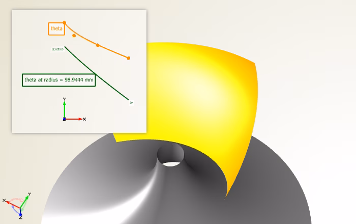
Radial Functions
Don’t modify each blade section separately, this is a tedious and time-consuming process. Instead, set up radial function graphs for all the 2D parameters of your profile, to intuitively control your mean camber characteristics in radial sweeping direction. Use any curve type or mathematical definition for such a function graph — with this design concept, literally everything is possible, and it saves so much time!
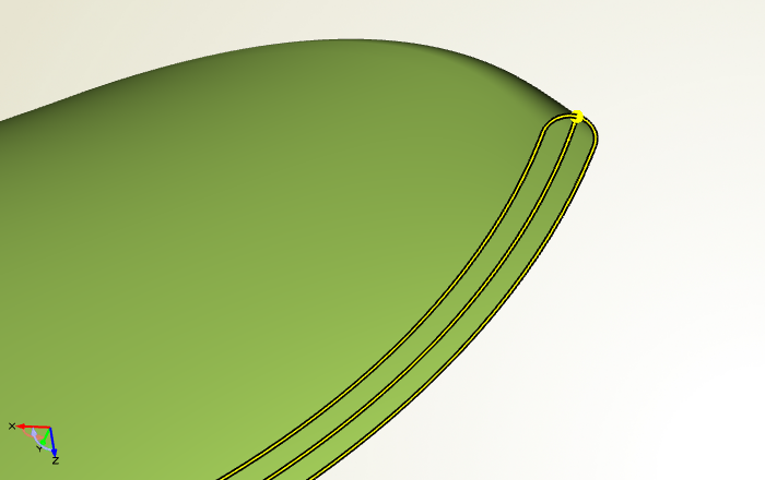
Thickness Definition
The same counts for thickness: Fully customize your 2D thickness curve only once, and then control it intuitively for the entire 3D blade shape using function graphs. Define circular and ellipse-shaped leading edges, or any other mixed flavor of it … it’s up to you!
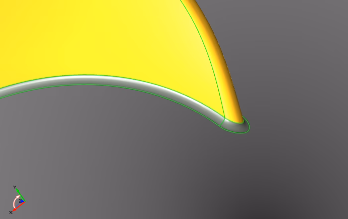
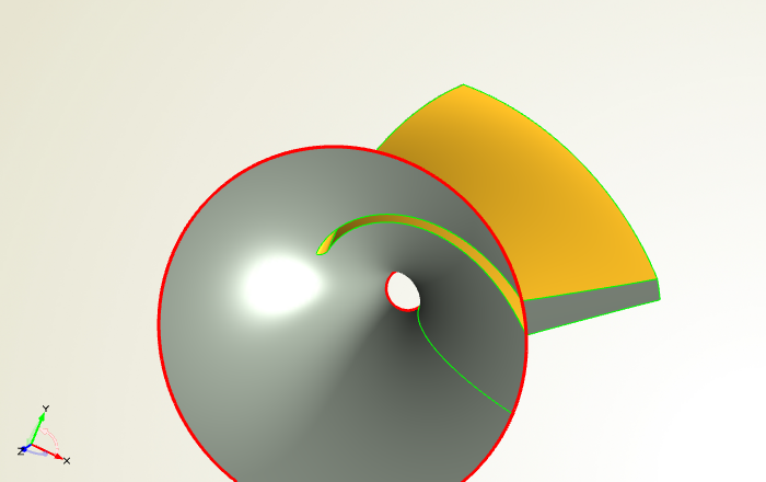
Simulation-Ready
Important for analyzing the blade shape with CFD: Receive simulation-ready geometries of your blade model, where convenient Boolean operations generate clean and watertight data for you!

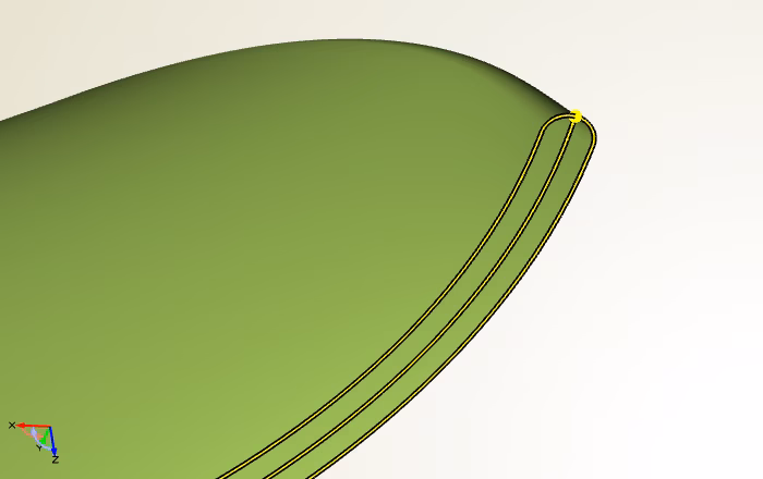
Fillet Modeling
CAESES® also offers you standard CAD functionality such as fillet modeling so as to quickly finalize your product designs. Now you are fully equipped with everything you need for high-end blade design!
Automation
With a single click, you can create a manual design candidate of your blade model that is managed next to your baseline design. Even better, let CAESES® do the job for you and automate the design creation process. In this last step, you can also plug-in your simulation tool, to calculate the performance of each design automatically (while you are enjoying some drinks on the weekend ;-) …).