CFD-Driven Shape Optimization of Turbine Blades and Endwall Contouring
![]() A gas turbine is a type of internal combustion engine that can be used to produce shaft work output, e.g. for driving an electric generator. In one of our recent projects with SIEMENS, we developed an easy-to-use and highly efficient workflow for the optimization of blade designs for stationary gas turbines, including endwall contouring.
A gas turbine is a type of internal combustion engine that can be used to produce shaft work output, e.g. for driving an electric generator. In one of our recent projects with SIEMENS, we developed an easy-to-use and highly efficient workflow for the optimization of blade designs for stationary gas turbines, including endwall contouring.
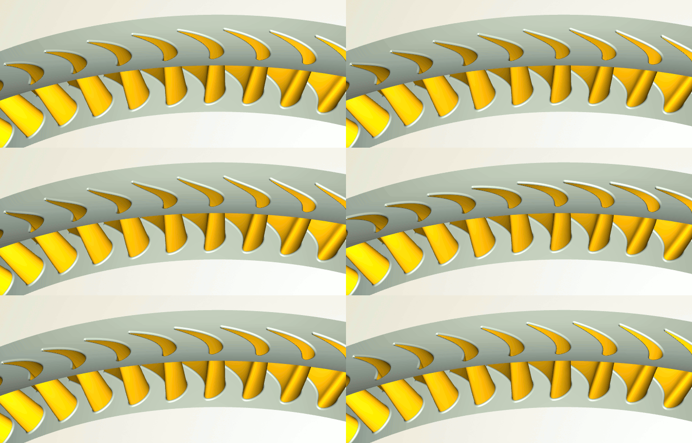
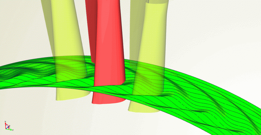
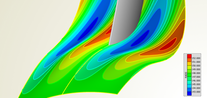
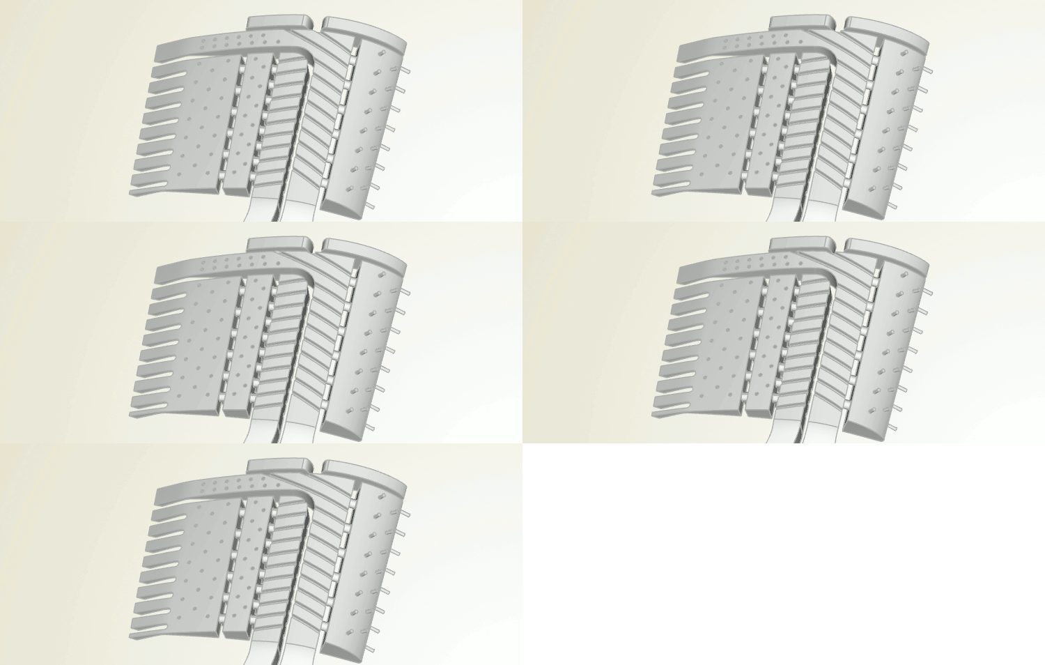
In order to be able to quickly run CFD-based shape optimizations for given initial designs, we first focused on variable and robust parametric models, both for the blade and the endwall contouring. The blade parameterization needed to be suitable for high-thickness, high-turning airfoils. For the endwall contouring, we created an efficient model that allows for a large bandwidth of variation using a very limited number of parameters. A trigonometric cross-section was defined by parameters like amplitude, phase, etc., while these parameters were controlled by smooth functions in the streamwise direction. See the following animation which shows an extreme variation of the phase.
SIEMENS wanted to be able to optimize either the blade only, or the endwall contouring only, or both at the same time. And, the entire design process needed to be as easy as possible, so that even engineers without any CAESES® knowledge are able to use it.
CAESES® offers so-called feature definitions for wrapping functionality in a script-like environment. In addition, CAESES® can be run in batch mode. These two capabilities allow high customization for CAESES® use, to fit into almost any existing design workflow. As a result of this customization, the final workflow was split into two separate stages:
An Easy-To-Use Workflow
In the first stage, the SIEMENS engineers simply run a script which references an initial turbine blade and flow path geometry. CAESES® is triggered in batch mode, and automatically fits the parametric model to the imported geometry, making use of parameter extraction and internal optimization steps. As a result, a new script file is generated, which includes all of the adjusted parameter values. The fitted CAESES® geometry model is now directly ready for optimization.
In the second stage, this automatically generated script file is controlled by the optimizer, which changes the parameter values for each variant and again runs CAESES® in batch mode to output the current variant’s geometry. In the optimizer, the engineers choose what components to optimize, which parameters to use and the considered objectives.
With this approach, we were able to create and introduce a highly automated design workflow, while at the same time the engineers of SIEMENS didn’t require any expertise with CAESES® – everything was controlled by very simple and readable scripts, from the initial fitting up to the optimization. Note that SIEMENS is not only able to visually inspect, but also to fully access and modify the geometry models and the fitting procedure through the CAESES® graphical user interface, in case they want to introduce changes to the parameterization or to the workflow.
Key Benefits
- Powerful and easy-to-use workflow for optimization of turbine blades and endwall contouring
- Robust and flexible variable geometry models for highly automated processes
- No big changes to the existing workflow
- No CAESES® expertise required for conducting turbine blade and endwall contouring optimizations
- No hard-coded functionality, models can be modified at any time, also by SIEMENS engineers
“We launched a pilot project with FRIENDSHIP SYSTEMS to evaluate CAESES® in May, it helped us solve a time-critical task in July and it became a design tool by October. By then we had created flexible and robust parametric models for complex parts, enabling us to optimize in design spaces we had previously not been able to explore.”
— Tilmann auf dem Kampe, Head of Aerodynamics Technology Development, Large Gas Turbine Engineering, SIEMENS
With kind permission of SIEMENS
PDF Download
There is a comprehensive presentation “Advanced 3D geometries for turbine applications” from the European CAESES® Users’ Meeting 2017.
More Information
Check out the blog post “Variable Geometry for Endwall Contouring of Turbines and Compressors” which comes with a nice demo video of a parametric endwall contouring geometry. There is also a video about axial turbine blade design which shows how such a model is set up, including parametric flow domains for automated meshing.
If you are interested in cooling structures, see the blog post “Turbine Blade Cooling” which comes with a few nice animations and some details about how to model these geometries.

