Die Casting Optimization with FLOW-3D and CAESES
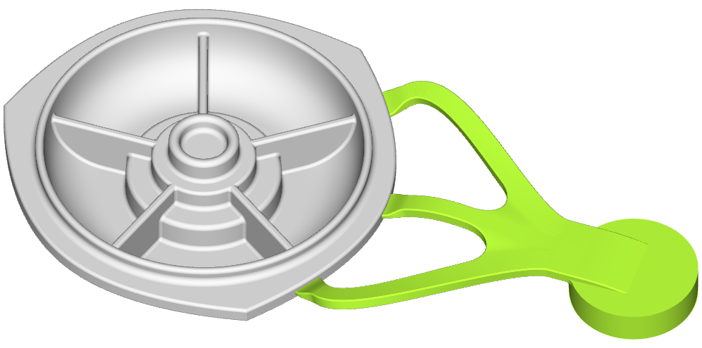
Die casting is a metal casting process where molten metal is forced into a mold cavity. We have worked on several projects in this field together with our partner Flow Science, the makers of FLOW-3D. For this case study, the shape of a die casting component was optimized. The parametric model – created in CAESES® with a set of 8 shape parameters – was coupled to FLOW-3D to calculate the relevant flow quantities which are used to define objective functions.
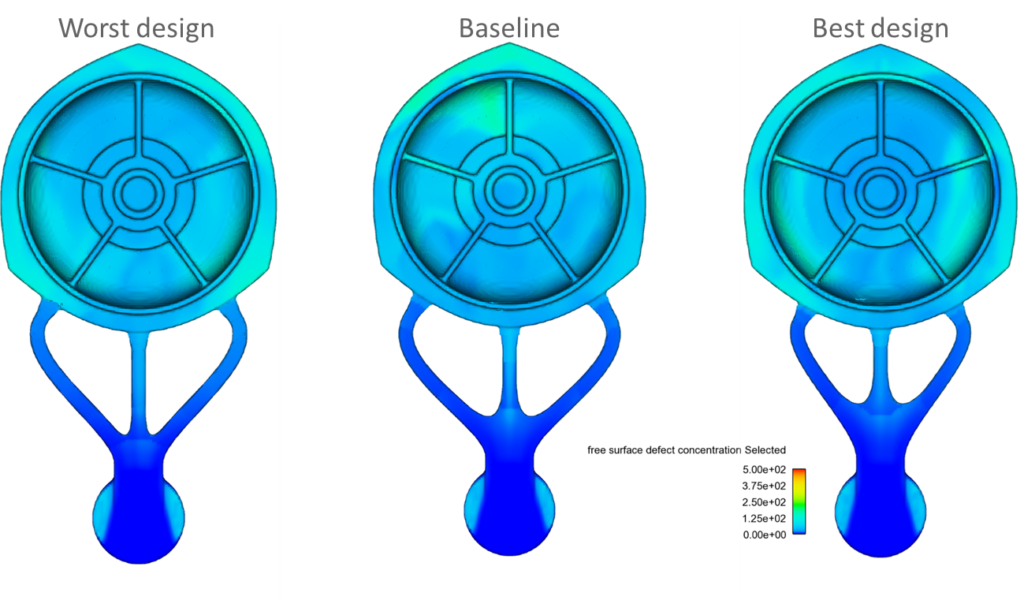
The main goal of this study was to reduce the overall entrained air volume. At the same time, the free surface defect concentration (these surface impurities arose from oxide formation on the free surface) should not be higher than for the baseline design. For this purpose, a fully-automated workflow was set up where CAESES® optimization strategies were used to generate and analyze different design candidates.
The Geometry Model
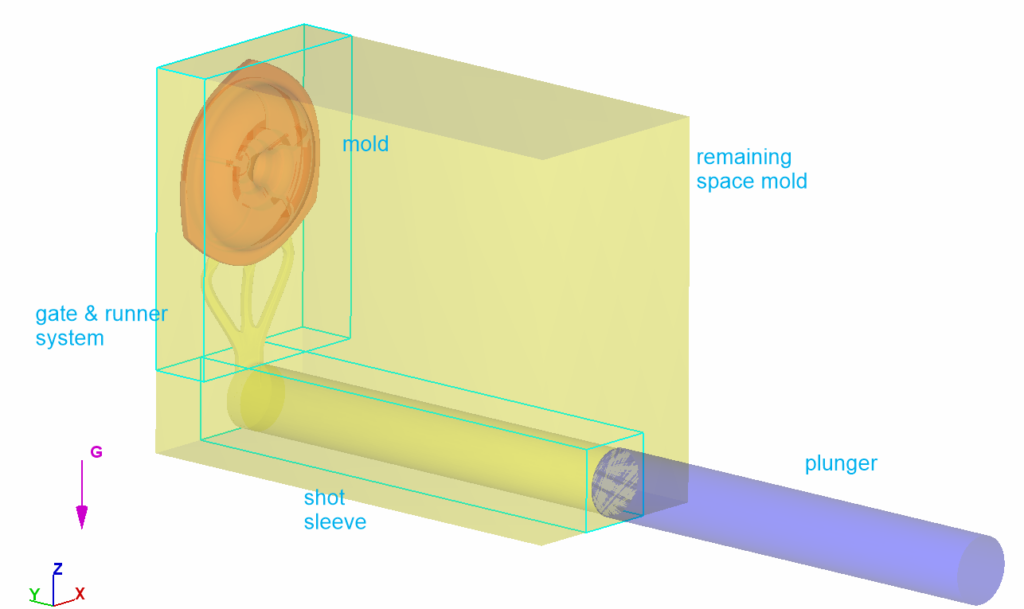
The initial baseline geometry was imported into CAESES® and a parametric model was rebuilt. The mold, runner and shot sleeve geometries were subtracted from a solid domain to produce a watertight flow domain that could be readily meshed in an automated workflow.
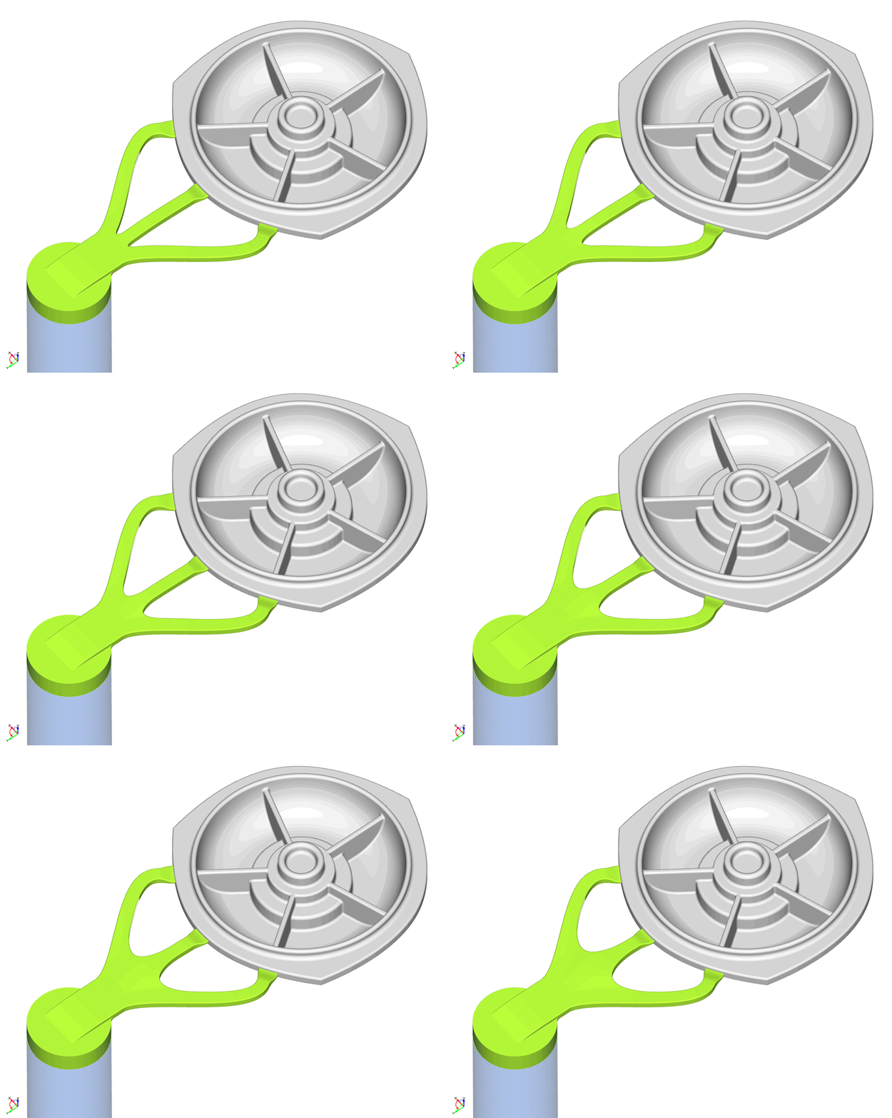
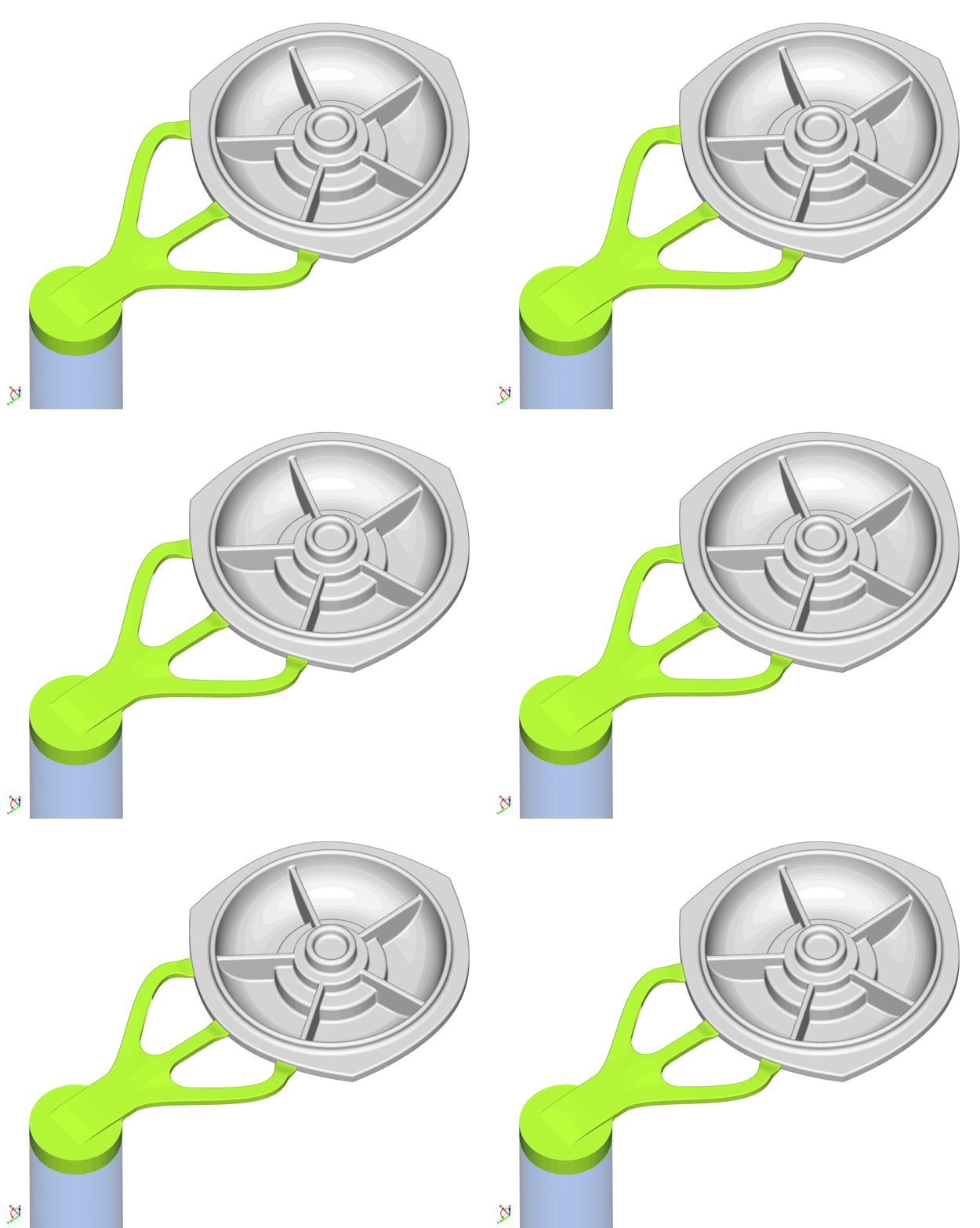
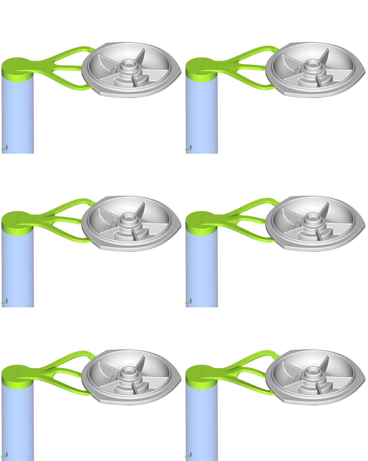
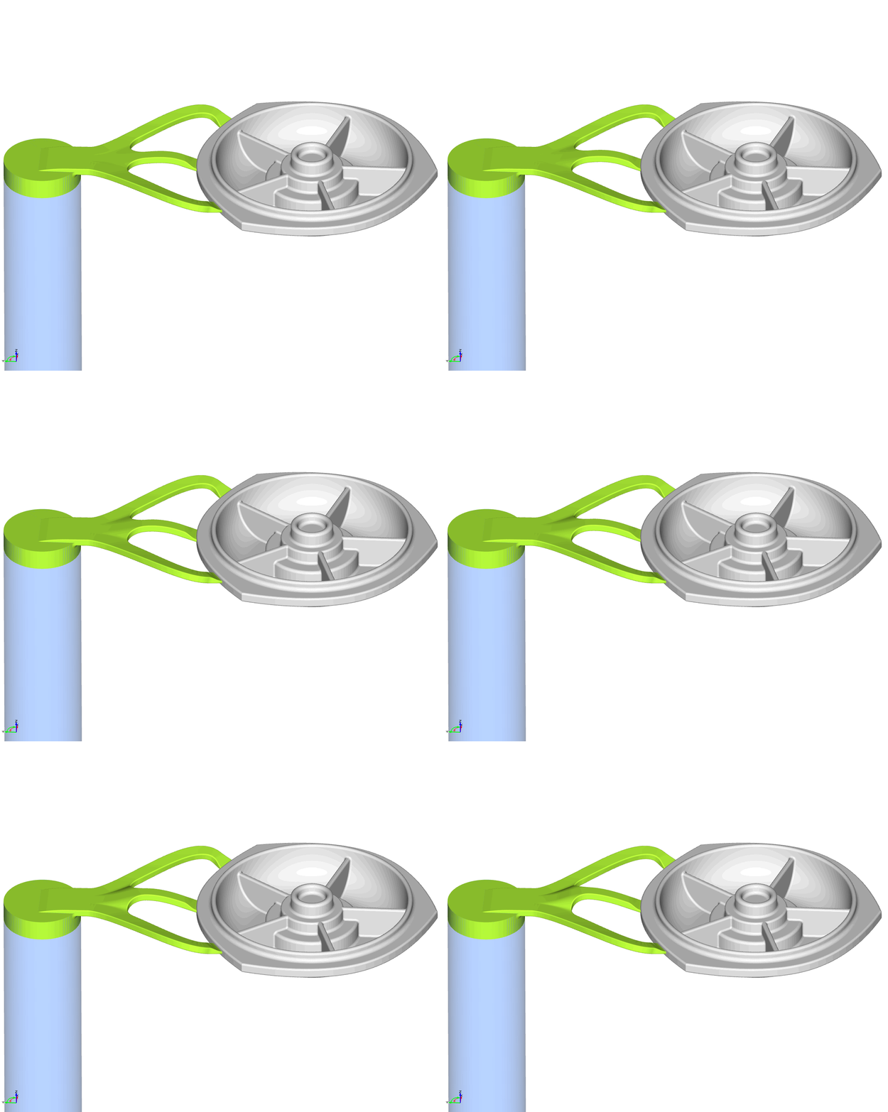
The lengths, some angles and other shape characteristics of the component were allowed to change. The following animations show some of the typical changes that got applied in the automated optimization:
Constraints
The velocity in the gates needed to be in the range 20-60 m/s. The gates should be fed by the runner system at the same time. All defects should go to overflows. The fast shot started when the metal hits the gates. The flow should also run from thin to thick sections, using the shortest route.
Automated CFD Calculations
The FLOW-3D setup was created once for the baseline design. Through the software connector of CAESES®, this setup could be automatically re-used for all new design candidates. Everything from material properties to number of mesh elements and density could be controlled by CAESES® during the investigation. The result data from FLOW-3D was automatically transferred back to CAESES® and used for calculation of objective functions.
Mesh Properties
A non-conforming mesh type was chosen with 2 blocks. The total number of real cells was around 1.400.000 with a cell size of 2 mm.
Simulation Properties
For the plunger, the material CuCuBe (Copper Die) was used which has a thermal conductivity of 300 W/(mK) and where density * specific heat is 3.52*106 J/(m3K). For the remaining space mold, steel H13 was taken, with a thermal conductivity of 28.6 W/(mK) and where density * specific heat is 3.56*104 J/(m3K). The maximum thermal penetration depth is 14 mm for this material.
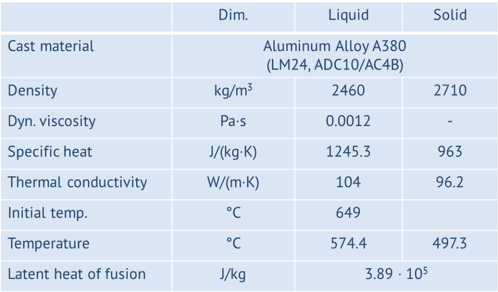
The simulation properties of the cast material are shown in the next picture:
One fluid was used with a free surface model and the following models were applied:
- Air entrainment
- Cavitation
- Defect tracking
- Density evaluation
- Gravity and non-intertial reference frame
- Heat transfer
- Moving and simple deforming objects
- Solidification
- Viscosity and turbulence
Results
The optimization was divided into two phases. In level 1, the basic flow quantities were optimized. The speed during the fast shot was varied in the range 1.5-2.5 m/s (baseline: 1.6 m/s). The casting fluid temperature was also studied and varied from 620°-680° (baseline: 649°).
After this initial optimization phase, the level 2 phase started. In this phase, the shape parameters were allowed to vary within an automated optimization.
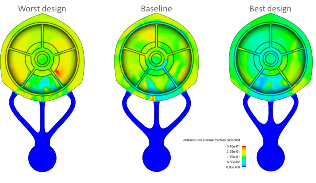
As a result of this study, the entrained air volume could be improved by 15% compared to the baseline design, while at the same time the free surface defect concentration was also slightly improved by 1%. Note that the free surface defect concentration was not part of the objective function. The following pictures finally show some of the results:
More Information
For the design and shape optimization of casting components, CAESES® is your ideal tool. Geometry modeling, CFD coupling and optimization – all in a single solution. FLOW-3D is easily coupled to CAESES®, but any other simulation package can also be integrated. Just let us know if you have any questions.

