CFD-Driven Shape Optimization of a Control Valve
Control valves are used in a wide range of industries, and they regulate the flow of various fluids. For a project at ARCA Valves, an optimization needed to be carried out for a DN700 control valve for liquid and gaseous media, optimized for use as an anti-surge valve on turbocompressors.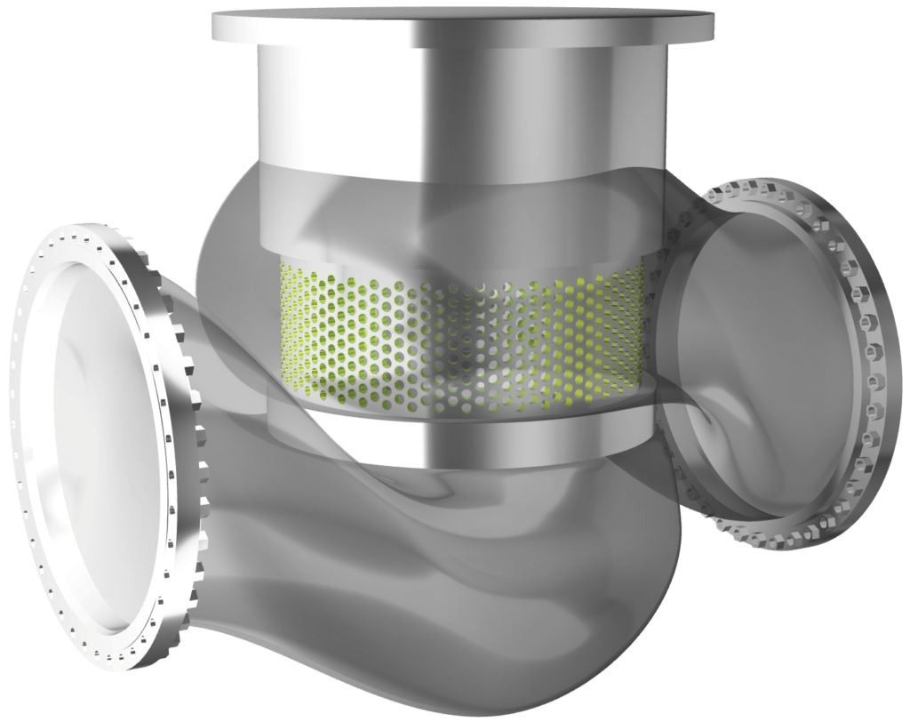
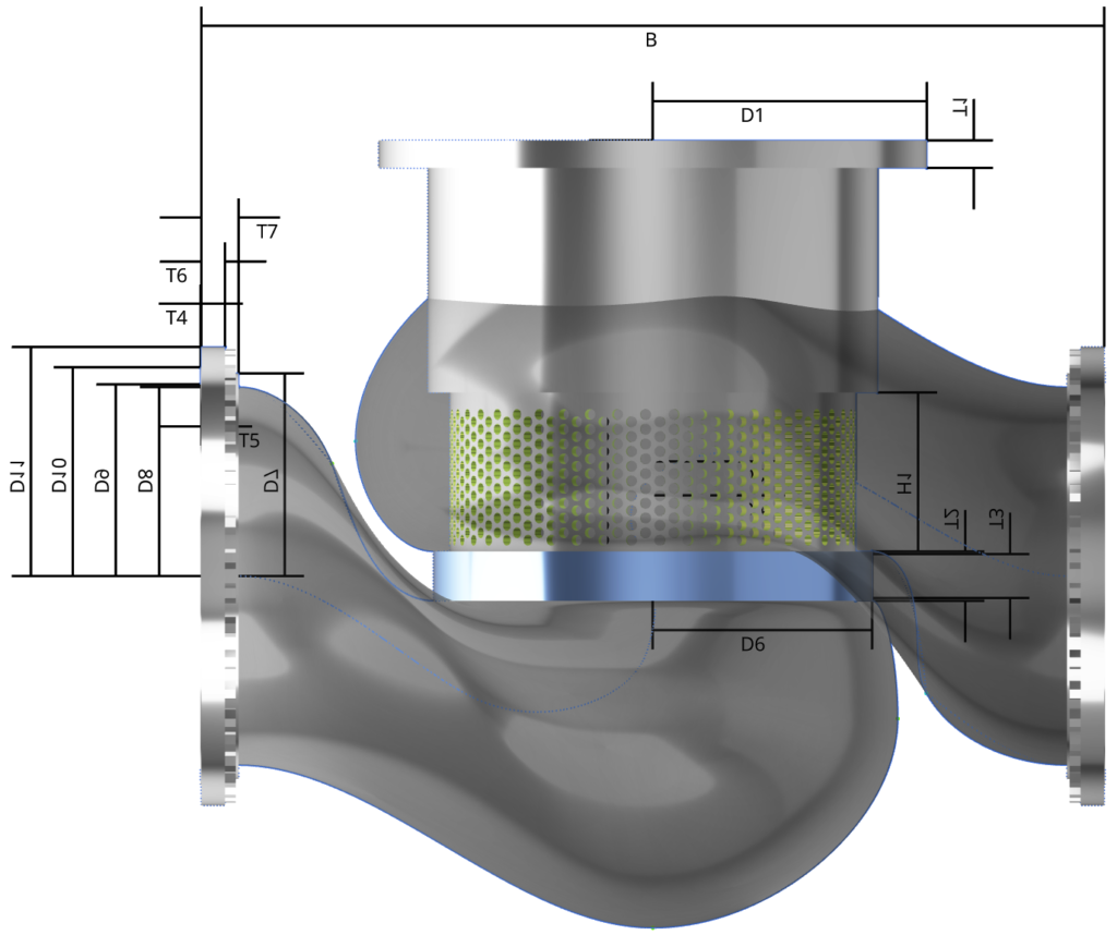
The challenge was to design a flexible parameterized geometry model of the valve housing that additionally incorporated a set of constraints (wall thicknesses, flange definitions).
For the CFD part, Autodesk CFD was used. The parametric geometry model was created within CAESES.
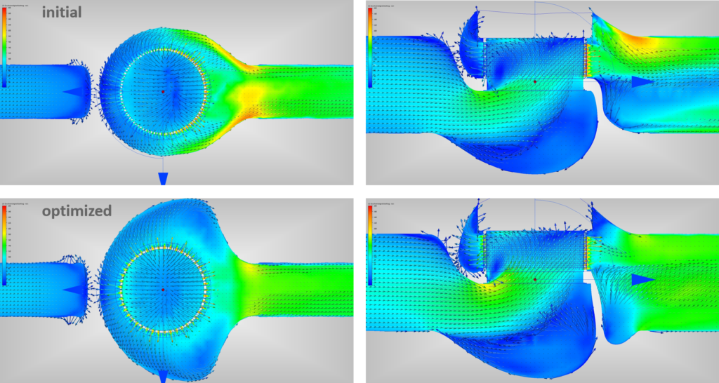
The target of the optimization was a high flow coefficient Kvs, to exceeds the delivery capacity of the turbocompressor and allow the gas trapped inside the pipelines and heat exchangers to be relaxed in a very short time span upon safety shutdown of the compressor. The operating condition was the relaxation of an ideal gas with a pressure ratio of 0.7 across the valve and flow direction ‘flow to open’.
Geometry Modeling and Variation
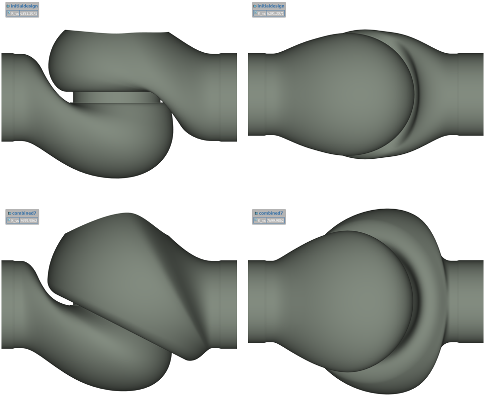
Inlet and outlet channels of the valve were controlled by parameterized upper and lower contours, resulting in a sweep path, along which an elliptical cross-section was swept. One ellipse axis of the crossection was defined by the distance of the channel contours, while the other one could be varied freely. The flange positions, plug seat ring and cage geometry were fixed, but the seat could be moved vertically.
Key Benefits
- Improvement of the flow coefficient Kvs by approximately 25% compared to initial conventional design.
- Target Kvs surpassed by ~3%.
- The development time could be greatly reduced (about two weeks for setting up and running the optimization).
- The approach allowed for the exploration of unconventional concepts.
- The need for physical testing could be greatly reduced.
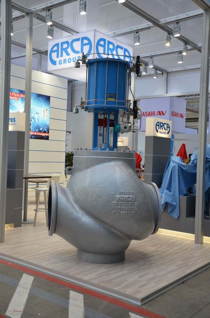
The final valve
With courtesy of Hans-Joachim Dappen, Arca Valves

