
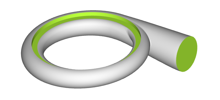
What are Volutes?
Volutes are integral to most radial turbomachines, for which a variety of cross sectional definitions can exist. The cross section is the 2D curve that is swept along the circumferential direction. Generally, volutes can be found in pumps and turbochargers, together with a rotating impeller in the center of the scroll. For pumps and compressors, the volute has the function to convert kinetic energy into pressure by reducing the fluid’s speed and increasing pressure, while turbine volutes have the opposite function i.e. converting exhaust gas pressure into kinetic energy (to drive the impeller).
What Is the Challenge When It Comes to Volutes?
The design and the systematic flow optimization of such a volute can be a time-consuming task. Often this is an iterative process where the CFD engineer is analyzing a new design candidate that was previously prepared by the CAD department. After the analysis, the CFD engineer gives recommendations to the CAD colleague on how to change the shape. The CAD expert adjusts the model according to this input, and returns the geometry back to the CFD engineer. This is a typical loop, and it can take several days to weeks until a new and improved volute is developed. Things can even get more complicated, having in mind that other components also need to be considered (such as impeller and diffuser) to have more exact performance predictions.
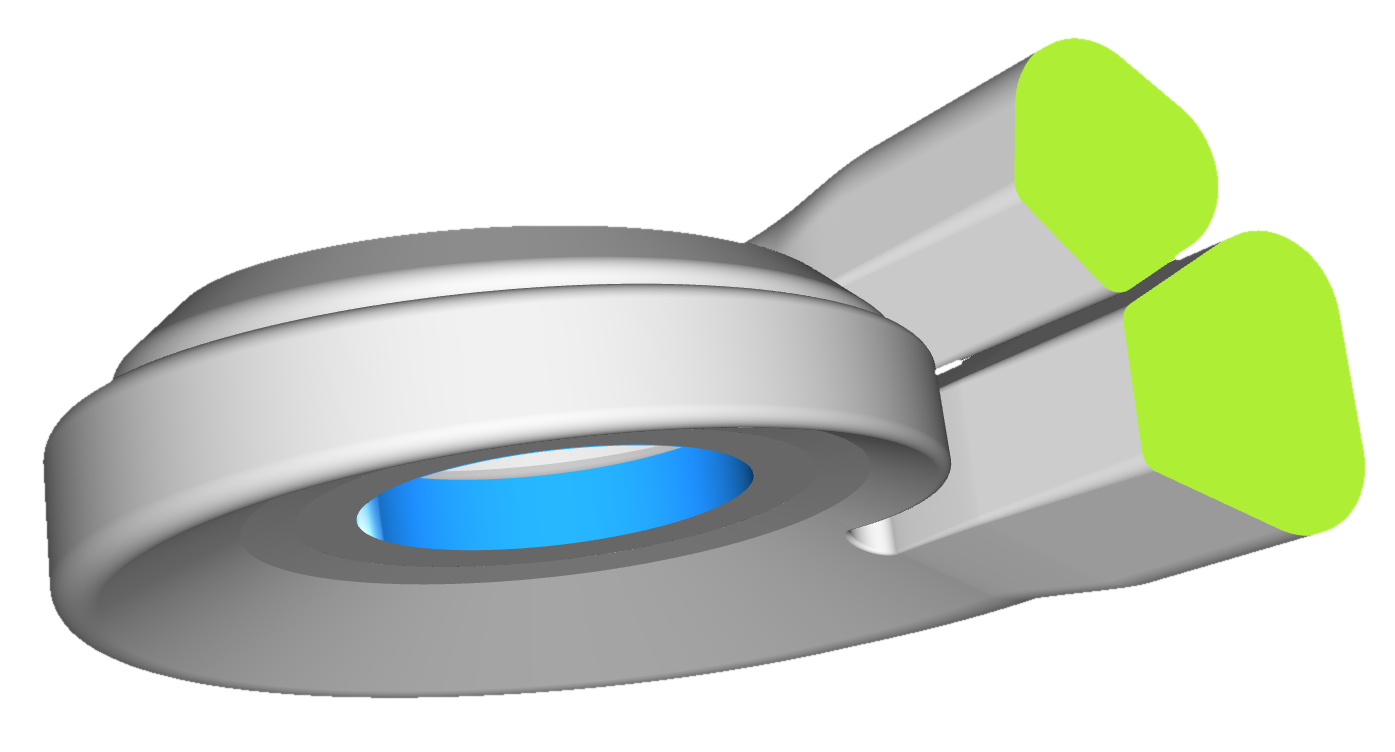
Generate new design candidates of complex twin scroll volutes with a single click
CFD-Ready & Variable Volute Models
The solution for this expensive development process is to focus on specialized volute models for CFD engineers. In other words: Intuitive parametric models that can be readily used in the CFD department for design studies, and that directly address a CFD-centric thinking. These intelligent models are set up in the specialized software CAESES®, either by yourself or through support by FRIENDSHIP SYSTEMS. Generally, volutes are tailor-made for each customer and contain all the parameter controls according to the company’s know-how and requirements.
Create models with high flexibility and robustness
Cross Section Definition
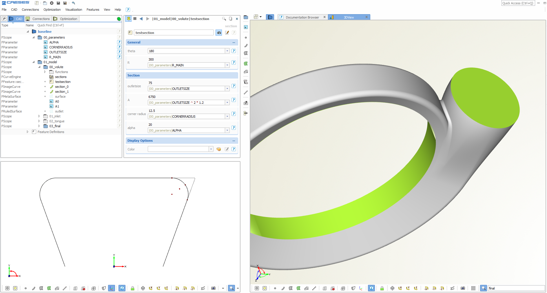
For custom 2D definitions of cross sections, you can make use of the feature technology in CAESES®: Create custom curve types that have individual input parameters and which are parametric! The following screenshot shows a typical cross section definition:
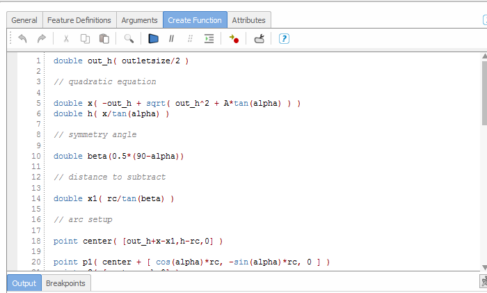
User-defined cross section definition
In many cases the volute is controlled by typical distributions such as A/R ratio – no matter what kind of 2D cross section is required for the design. CFD experts typically want to try out their own ideas, having in mind more flow-related shape controls. These ideas and also fixed packaging constraints can be directly built into such a volute model. You can even use optimization strategies in these feature definitions, e.g. to keep a fixed A/R ratio – as shown in the animation below:
Parameter changes of a cross section while keeping a fixed A/R ratio
With the help of specialized surface technologies, you can introduce custom function graphs for each 2D section parameter (e.g. for the parameter “Weight 3” in the animation above), to receive an effective and parameter-reduced shape control with regards to the circumferential direction. The function graphs ‘f(phi)’ are typically bspline curves (of any degree) or mathematical expressions. Both is possible in CAESES®. There is no tedious manipulation of single cross sections, everything is controlled through function graphs and global parameters, resulting in smooth and feasible designs.
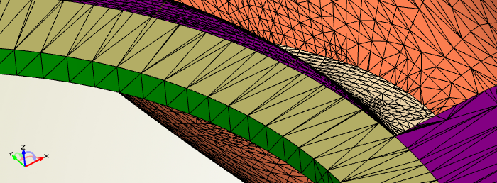
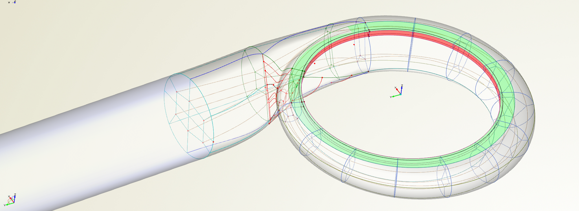
Tongue Modeling
When you ask CAD engineers that cope with volutes “Which is the most difficult part to model?”, they will probably tell you: the tongue part! This is the region where the main volute surface intersects the inlet (turbine) or outlet (compressor) geometry, respectively.
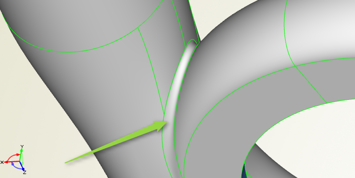
Modeling of robust and variable volute tongues
There are various techniques and solutions in CAESES® which solve this tricky task for you. This tremendously accelerates the modeling process of tongue geometries, and makes the final volute robust during variation. If you are looking for detailed tongue optimization, you can dig into these techniques and modify your geometry model. CAESES® models are no black box, everything can be accessed, modified and adjusted to your requirements.
How It Works
Check out this video (11 min.) in which the basic surface generation process is illustrated. The blog post “How to Create a Volute in 10 Steps” guides you through a complete volute design process.
How to create a volute in 10 steps: Automated robustness check
One-Time Pre-Processing for Automation
Since CAESES® is a solution that is dedicated to simulation engineers, it supports special coloring mechanisms for assigning boundary information to each patch. This helps you to detect inlet and outlet patches in your meshing & CFD software. CAESES® exports colored STL as well as special versions of colored STEP and IGES files. Pre-processing tasks are one-time tasks in CAESES® – do it for the baseline design and it will be automatically applied to all generated variants. This will drastically reduce your engineering time and it makes your geometry ready for automated processes.
Automate Meshing
CAESES® also allows you to create support geometry for automated generation of structured meshes. The additional inner geometry can be made of parametric curves which automatically adjust if the design variables of the volute model are changed. More information about this topic can be found in this short tech brief (PDF).
CAESES® models can be directly coupled to any meshing software. In particular, there are interfaces for connecting GridPro, Pointwise, NUMECA meshers, ANSYS meshers including ICEM CFD, and STAR-CCM+ meshing. With these convenient coupling interfaces, the mesh automation only takes a few clicks within CAESES® once the setup for the baseline design is ready.
Parametric support geometry for automated meshing
Design Studies and Shape Optimization
Besides a manual creation of new design candidates, the main focus is the process automation for design studies and formal optimizations. All volute models are 100% robust and hence perfectly suited for automated processes. This is actually where the fun starts – the ultimate strength of CAESES®. If needed, you can set up additional parametric support geometry for the meshing process such as auxiliary curves that serve as rails for block meshes in a structured mesh procedure.
Since CAESES® does not only create geometry but also offers you the possibility of integrating your meshing and CFD tools, you have everything at hand for full automation of your design process. And if you want to take it to the next level of including the impeller as well: simply use your simulation-ready CAESES® impeller model!
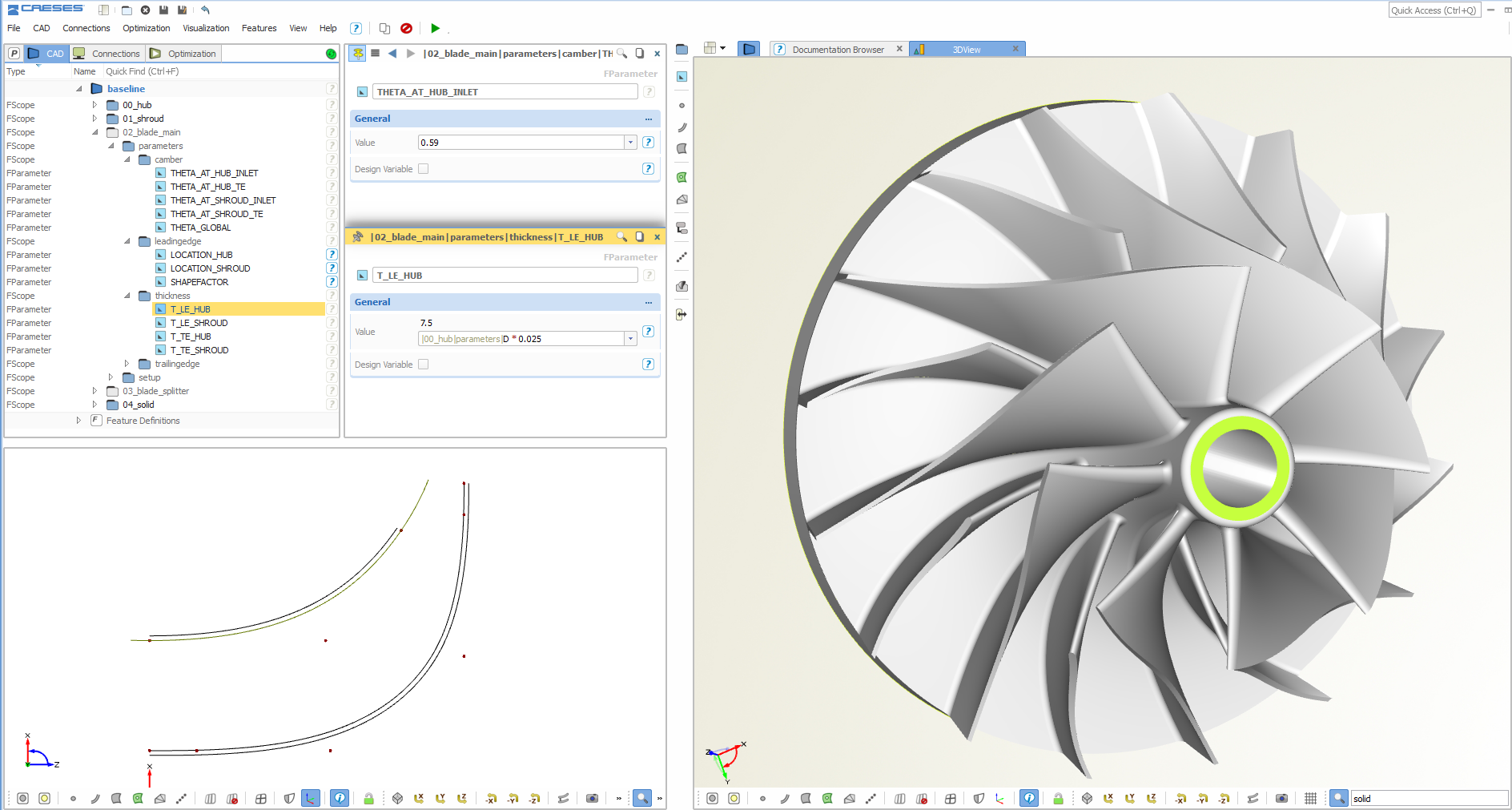
Include other components along with your volute, such as a variable impeller model
Online Demo
There is a volute model online for testing purposes. You can change parameters such as the area ratios and some additional tuning parameters. The final geometry can be downloaded as STL and STEP so that you can check it e.g. in your meshing system. Inlet, outlet and the remaining surfaces are colored differently so that these patches can be addressed with scripts for automated meshing.
VOLUTE
Check out this online demo model of a CAESES® volute. The model is rather simple and comes with a reduced parameter set. STL and STEP can be downloaded.
Download Tech Brief
A short summary of the CAESES® volute design capabilities can be found in this tech brief (PDF).