

For the fully-automated shape optimization with CFD, one key task is to robustly automate the geometry and mesh generation as well as the actual CFD flow analysis. Within one of our ongoing research projects, GAMMA, we recently had the challenge to automate the generation of a structured mesh.
Why Structured Meshes?
Compared to an unstructured mesh, structured meshes allow you to tremendously speed up the flow analysis, and they generally give you a better result accuracy. Both are great when considering the investigation of large design sets with a high analysis quality. However, in the context of optimization, generating an unstructured mesh can be automated more easily – just hand over the geometry and off you go. This is typically not the case for structured meshes. Why?
The Challenge with Structured Meshes
Well, the question is: How should your structured mesh actually look for an arbitrary shaped and feature-filled geometry? When considering e.g. volutes for turbochargers as given in our research project, there is a little feature in the geometry that is responsible for most of the headache – the tongue area. Here is a picture:
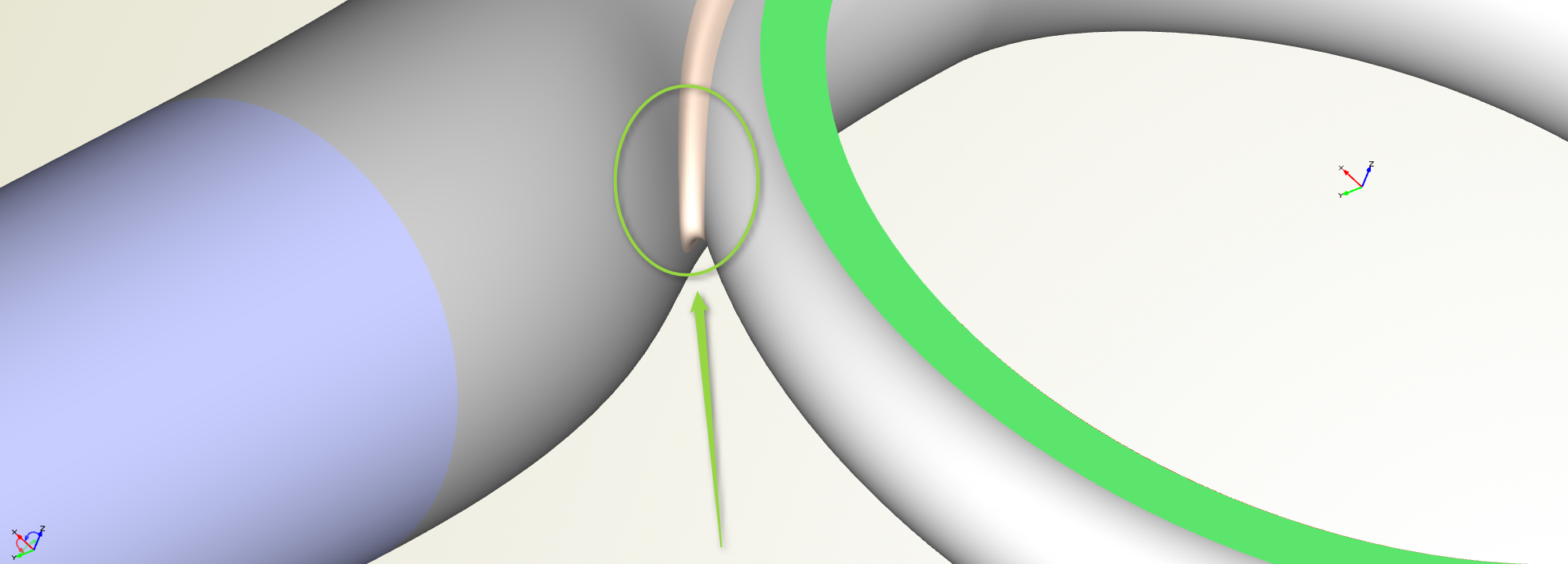
Where geometry comes together: The area that triggers the challenge when considering structured meshes
The tongue area is the location where the remaining geometry is merged. And then it gets a bit complicated for structured meshes. For the main geometry, the structured meshes can be defined quite well. Typically, you have a good idea what it looks like. But how should it automatically pass from the main geometry into the outlet area while having this tongue feature in between? There is some user information missing.
Support Geometry
If you think about how to generate a structured mesh in such a flow volume, you quickly end up with the common idea of providing some helpful information to your meshing system. You simply cannot do it automatically in a generalized way for all types of complex geometries. And this is what we did: Instead of only handing over a new design candidate to the meshing system, we also set up a parametric support geometry in CAESES® that serves as a guide for the block structures. It inscribes some sort of logic how the mesh will be organized. This support geometry is then transferred to the mesh process in addition to the remaining volute geometry. The next picture shows an example of such a support geometry setup (click on it to enlarge it):
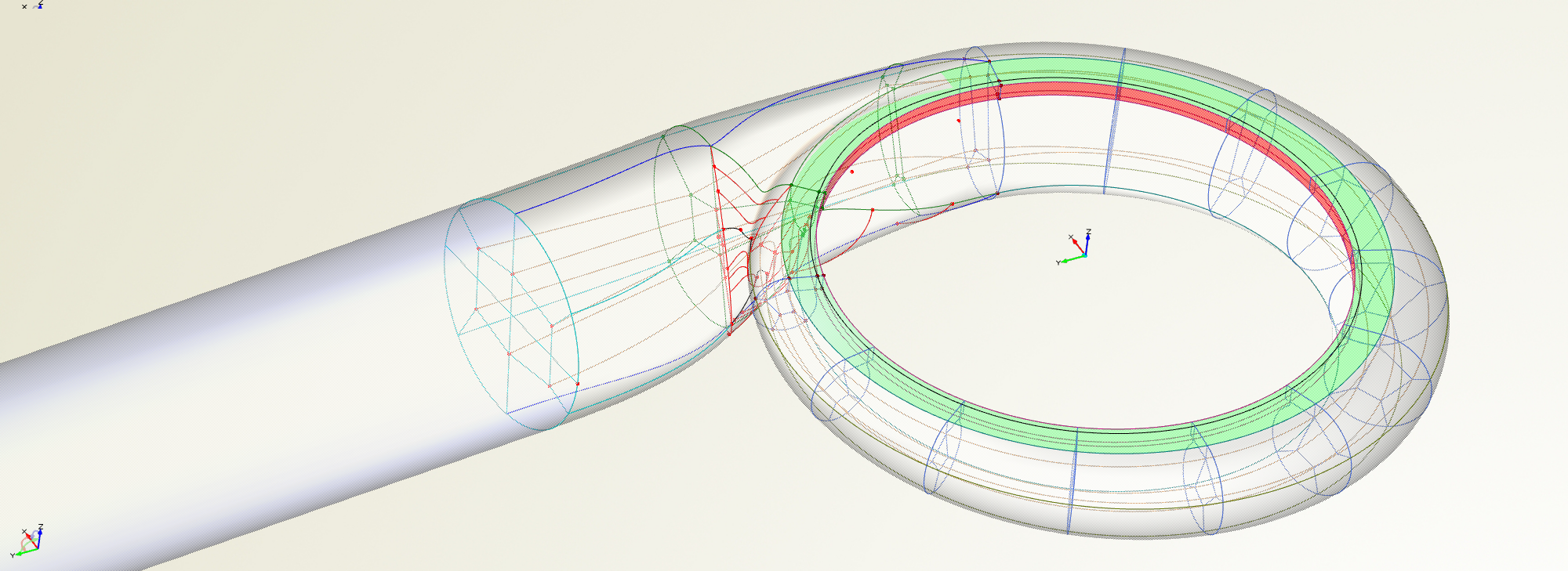
Parametric support geometry in CAESES for automated structured meshing
By means of this additional information, it is now possible to automate the structured meshing process for such a complex geometry. Since these inner curves are parametric objects and part of the volute model itself, they also change when you modify the design variables of the volute. This is also possible for the non-GUI (batch) run where the geometry is created through a script within an optimization, e.g. controlled by external optimization tools. This makes it directly suitable for use in HPC environments which is also a requirement in this research project.
Generalized Solutions
Setting up the support geometry is an additional task (plus creating the automation script that copes with it). However, if you do it in a smart way for one class of geometries, then you have a good chance to recycle it for future projects with similar geometries. A related example of such a support geometry is the periodic flow volume of turbomachinery blades. This is something the user sets up once and can then re-use it in all future projects, even though the blade shapes might look slightly different.
Parametric CFD flow domain for turbomachinery blades
Download Tech Brief
A short summary of the CAESES® meshing automation capabilities can be found in this tech brief (PDF).
Follow Us
Do you work on similar tasks? What is your experience with it? Feel free to share your thoughts on this blog post. If you are interested in stories like this and in CFD-driven design optimization, then sign up for our newsletter. Don’t worry, we won’t bother you with too many emails. Of course, you can unsubscribe at any time 🙂