Fast and Efficient Geometry Optimization with Morphing
While some geometry morphing methods have always been available in CAESES, mostly being used in maritime applications, the focus of the majority of our customers was put on fully parametric modeling. Each one of these approaches bears its own advantages and disadvantages, and with our recent release of CAESES 5, we devoted significant resources to specifically tackling the existing disadvantages of morphing in previous CAESES versions, in order to make this approach more appealing for a wider range of applications and be able to draw a bigger benefit from its advantages.
Morphing vs. Parametric Modeling
Fully parametric modeling is the generation of a parametric model for the complete geometry, or at least a component thereof, from scratch. We speak of fully parametric modeling because the parameters define all features of the final geometry. Some parameters may be at a high level like the length, width, and height of an object. Other parameters may determine details like a tangent angle or curvature at a particular location. A parametric model can be looked at as a system that takes parameters as input and produces a shape (variant) as an output.
Fully parametric modeling is very powerful, since it enables both large changes in the early design phase and small adjustments when fine-tuning at a later point in time. It provides very detailed and exact control over shape properties. Also, it facilitates the integration of constraints (e.g., related to packaging or manufacturing), allowing for a variation of the geometry while automatically conserving certain required properties. However, it surely doesn’t come as a surprise that setting up a fully parametric model is more time consuming and can require a tangible level of knowledge about modeling techniques, as well as the product and its behavior.
In morphing, sometimes also called partially parametric modeling, we deal with the (parametric) deformation of an existing, imported geometry. Hence, only the changes to this existing shape are defined by parameters, that can be controlled to generate design variants.
Partially parametric models are usually quick, fairly easy, and intuitive to set up. When compared to fully parametric models, they typically contain less intelligence about the product, and it is generally more difficult to excite large modifications. As we parameterize the changes to the geometry, they might only provide indirect control over shape properties and it can be challenging to integrate constraints.
Morphing before CAESES 5
Before version 5, CAESES provided the following selection of geometry morphing capabilities:
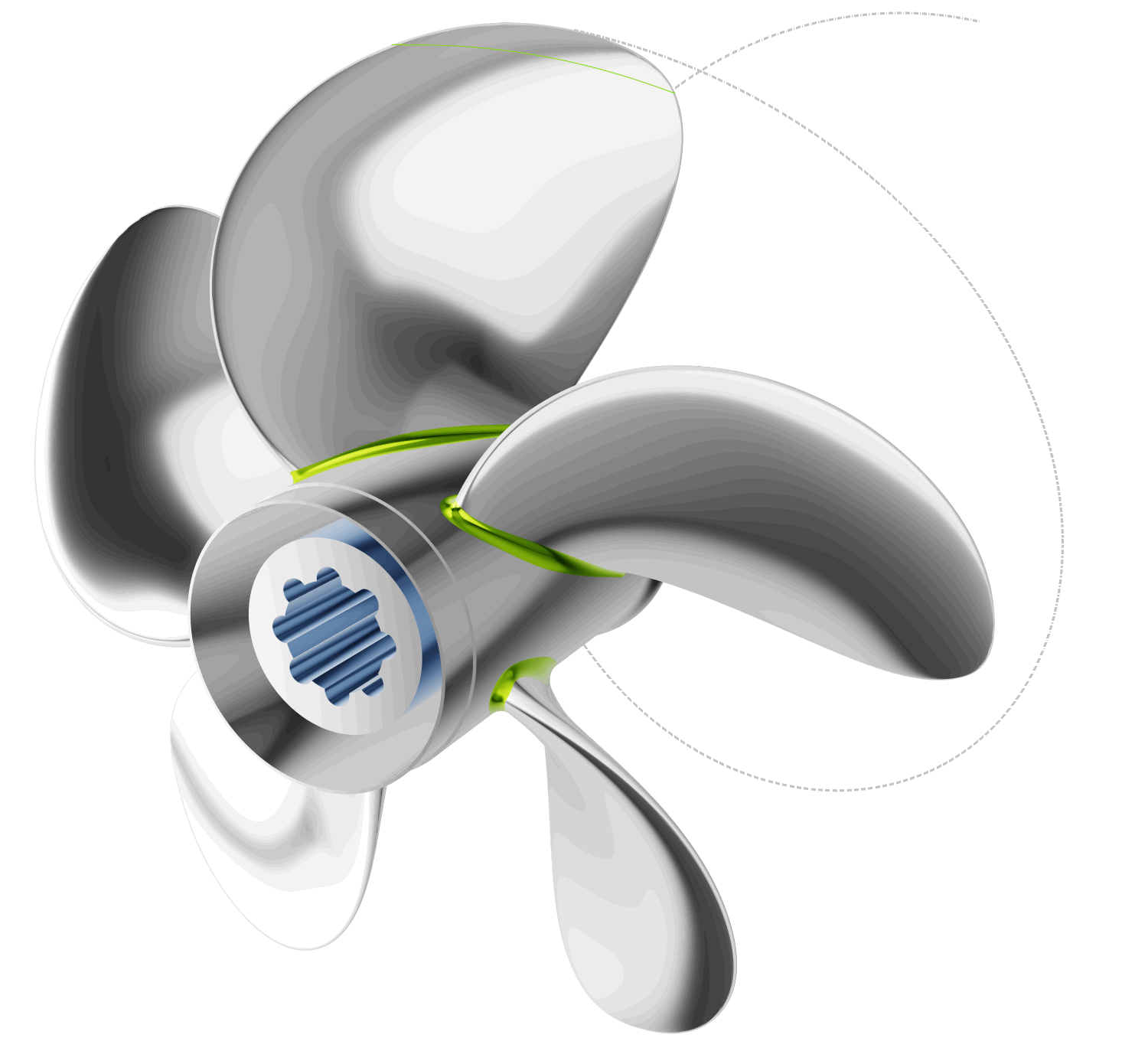
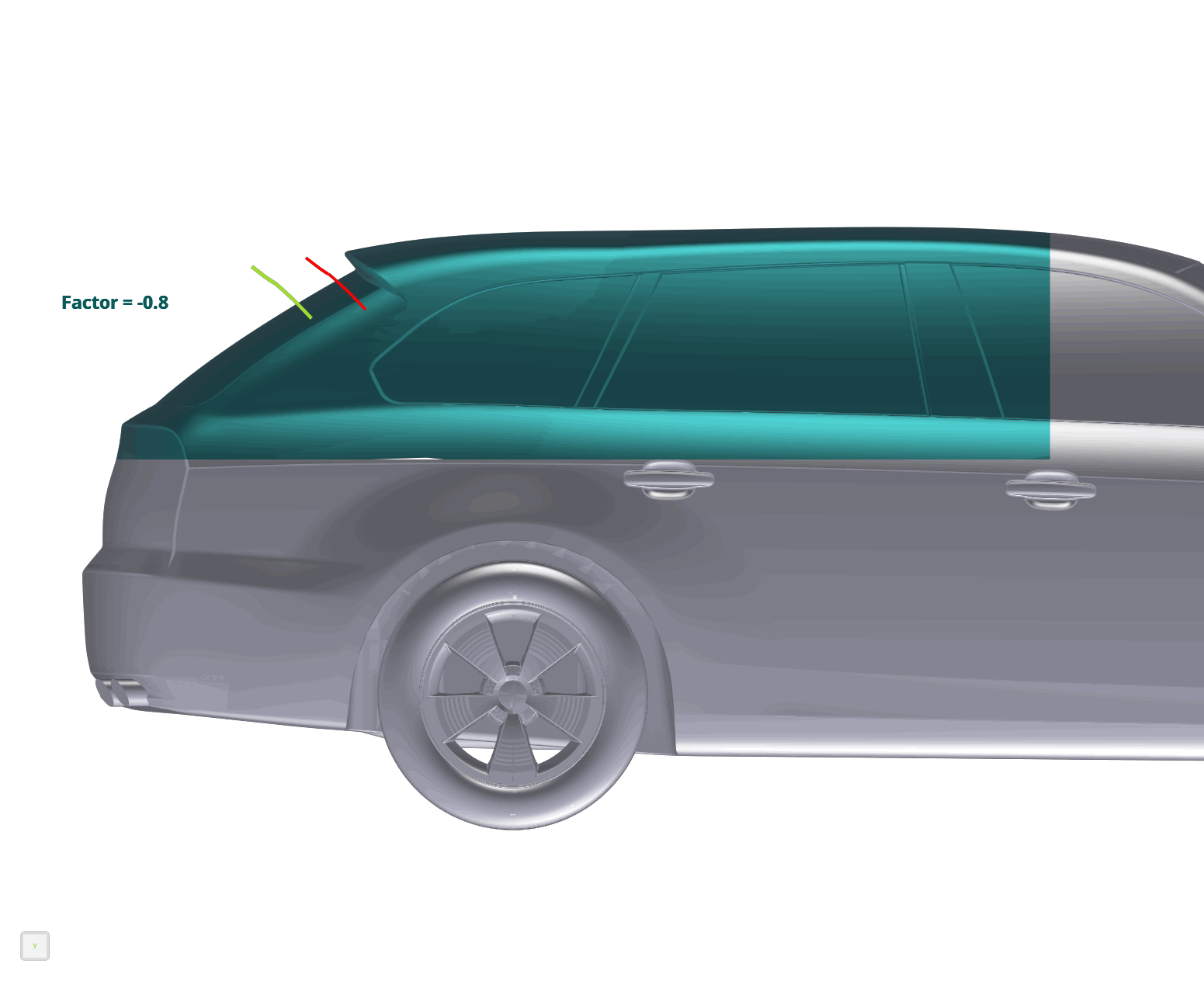
- Shift transformations change any point of the geometry by adding a certain displacement depending on the point’s initial position. The displacement can be a specified as a 1D (curve) or 2D (surface) function. Shift transformations can be concatenated, directly summed up and/or multiplied to form complex modifications.
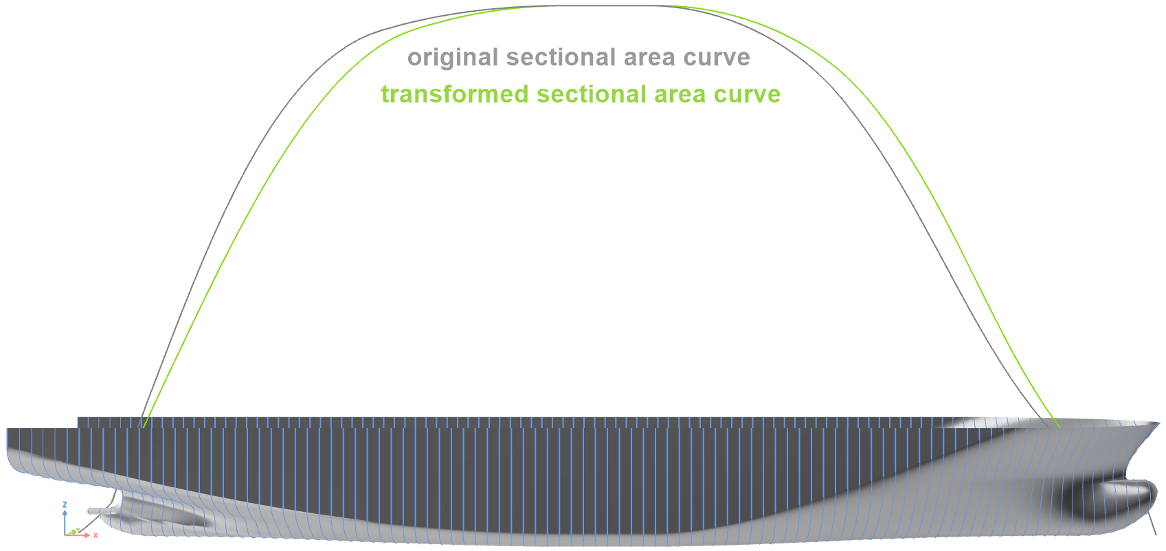
Their primary downside is that the displacement is limited to a fixed direction, specifically, one of the principal axis directions in CAESES, and therefore only make sense for appropriately oriented geometries. - The Lackenby shift is a special case of a shift transformation dedicated to maritime applications, where the displacement function in longitudinal direction is automatically determined. Its purpose is to modify the displacement volume of a ship hull and its distribution. In comparison to the classic Lackenby shift described in literature (LACKENBY, H (1950), On the Systematic Geometrical Variation of Ship Forms, Trans. INA, Vol. 92, pp. 289 – 315) the implementation in CAESES provides additional flexibility and control over the transformation.
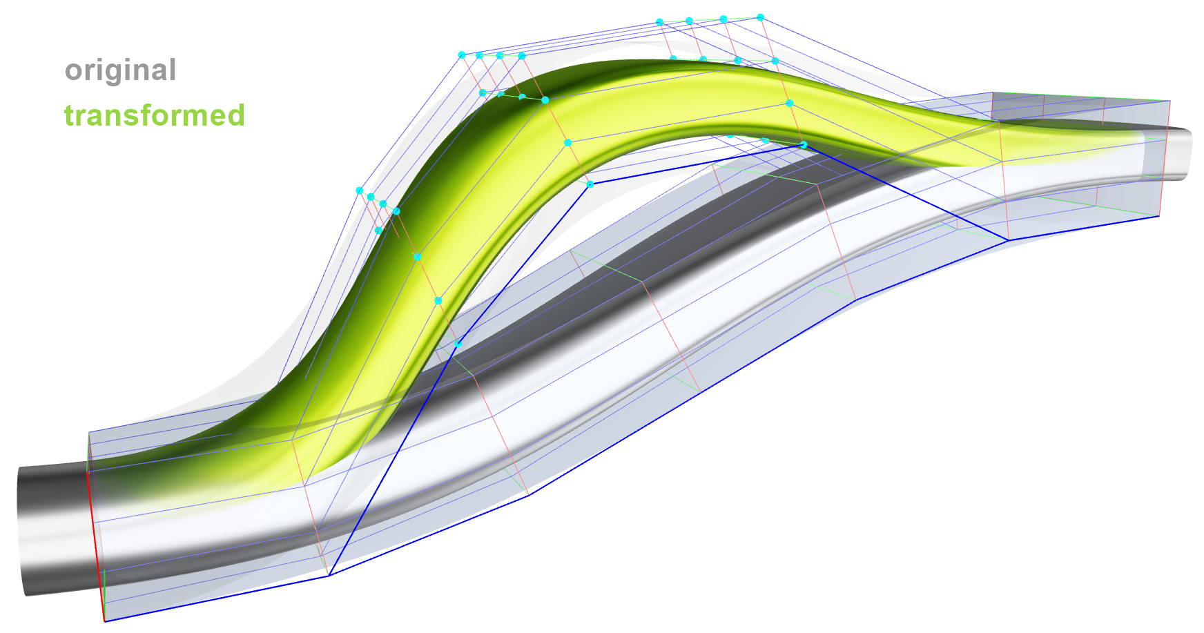
- In free-form deformation (FFD), also known as box deformation, the geometry to be modified is enclosed by a box consisting of a regular grid of vertices (i.e., rows, columns and layers defining a B‑spline volume). For all parts of the initial shape located within the box, a local coordinate triplet can be determined. By moving any of the vertices, or several of them in a concerted way, the box changes its shape and, along with it, the baseline is transformed.
FFD is very flexible in terms of the deformations that can be achieved, but is a paramount example for indirect control, as it is basically impossible (for the user) to exactly predict a priori which effect the displacement of the box vertices will have on the actual geometry. Additionally, depending on the initial geometry, the generation of a suitable box might require a non-negligible effort. - Finally, so-called cartesian shifts and spot transformations were available. They basically consist of point sources at which a displacement is applied either in principal axis or an arbitrary direction. This displacement decays towards the border of a region of influence centered at the point source.
These transformation objects can be regarded as experimental implementations, and have probably never been used in a production situation, as they are cumbersome and impractical to apply in real-life optimization problems.


New Morphing Capabilities in CAESES 5
The motivation to revisit the geometry morphing capabilities for the CAESES 5 release was primarily based on reducing the existing disadvantages (in previous CAESES versions) related to the precision with which the user is able to control the transformation and therefore the final geometry, as well as removing the inherent restrictions of existing morphing capabilities that make them unsuitable for all applications. Additionally, morphing is a highly convenient tool for the novice user, who is not yet up to speed with parametric modeling techniques and wants to quickly optimize an already existing geometry. It should therefore be easy and intuitive to apply.
The guiding visions were a) to achieve a sort of “on-demand parameterization” in which the user is able to apply full parametric control, akin to a fully parametric model, to selected areas of an imported geometry, as well as b) a very easy-to-use interactive tool for quick shape modifications.
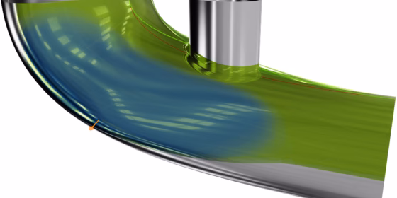
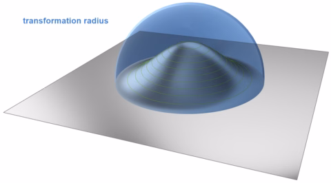
The new morphing toolset was based on so-called radial basis functions (RBFs). The RBF deformation technique is characterized by treating space deformation as an abstract interpolation problem: Given a set of displacements for a corresponding set of positions, the goal is to smoothly interpolate displacements through space. Within the RBF deformation approach the space deformation function is constructed as a linear combination of radially symmetric kernels, located at a set of centers and appropriately weighted. A second important aspect of RBF deformations is the kernel placement. By directly placing kernels on all handle and fixed vertices it is straight forward to implement a handle-based direct manipulation interface satisfying all constraints specified by the user easily and exactly.
CAESES supports both discrete (e.g., STL) and NURBS-geometries as objects for the deformation. The setup for both kinds of geometries differs in the details, but the underlying principle is the same and the usage is quite similar.
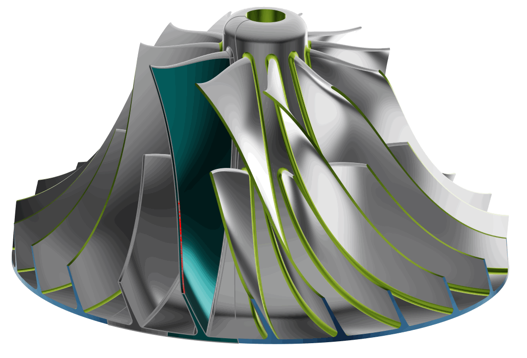
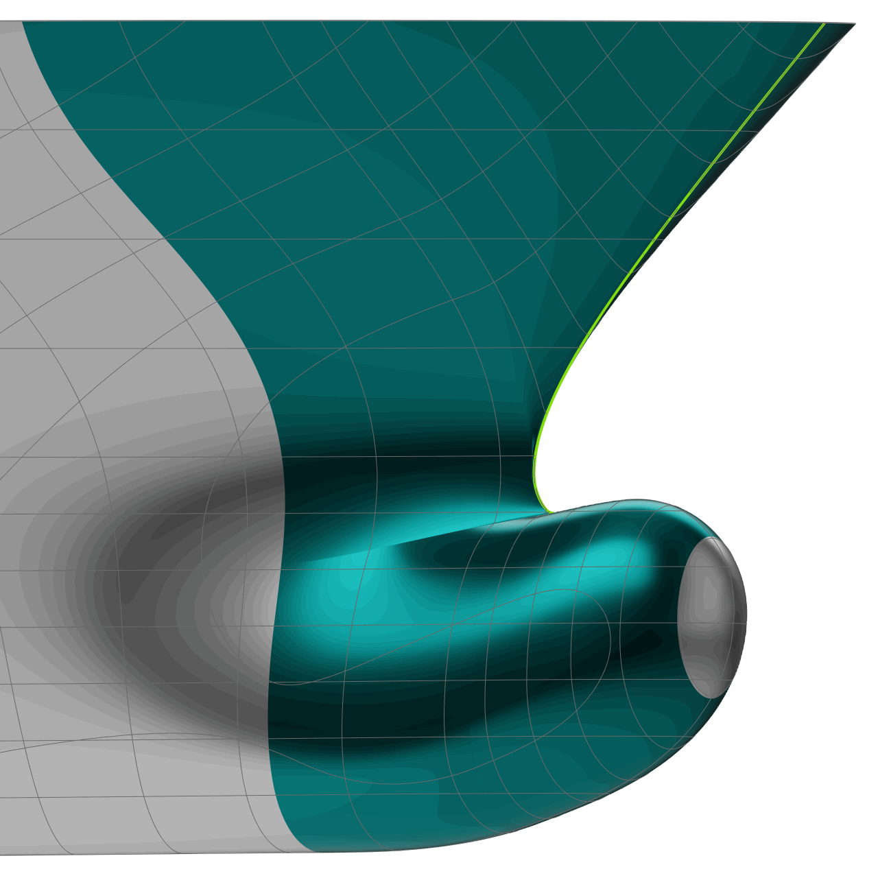
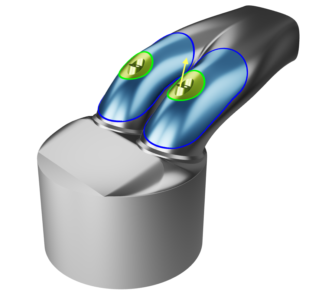
A geometry can have more than one transformation defined. In CAESES one such transformation is called an “RBF region”. First, the user needs to define an area of the geometry that may be freely deformed by the algorithm. In the case of discrete geometry, this can be done using the newly created interactive paint tool that allows for painting areas onto the geometry, while in the NURBS case the user may select faces from the boundary representation that will be subjected to the deformation. In the following, the area that was marked in this manner will be called the “deformation area”, while the rest of the geometry will be called the “fixed area”, since it will not be a part of the deformation.
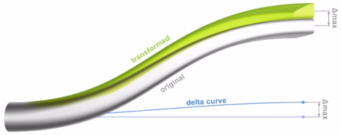
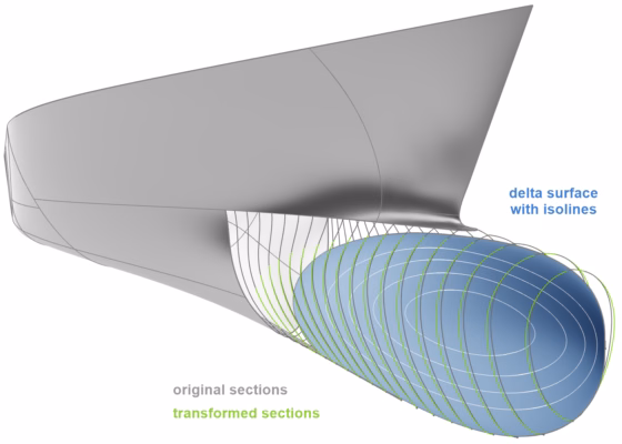
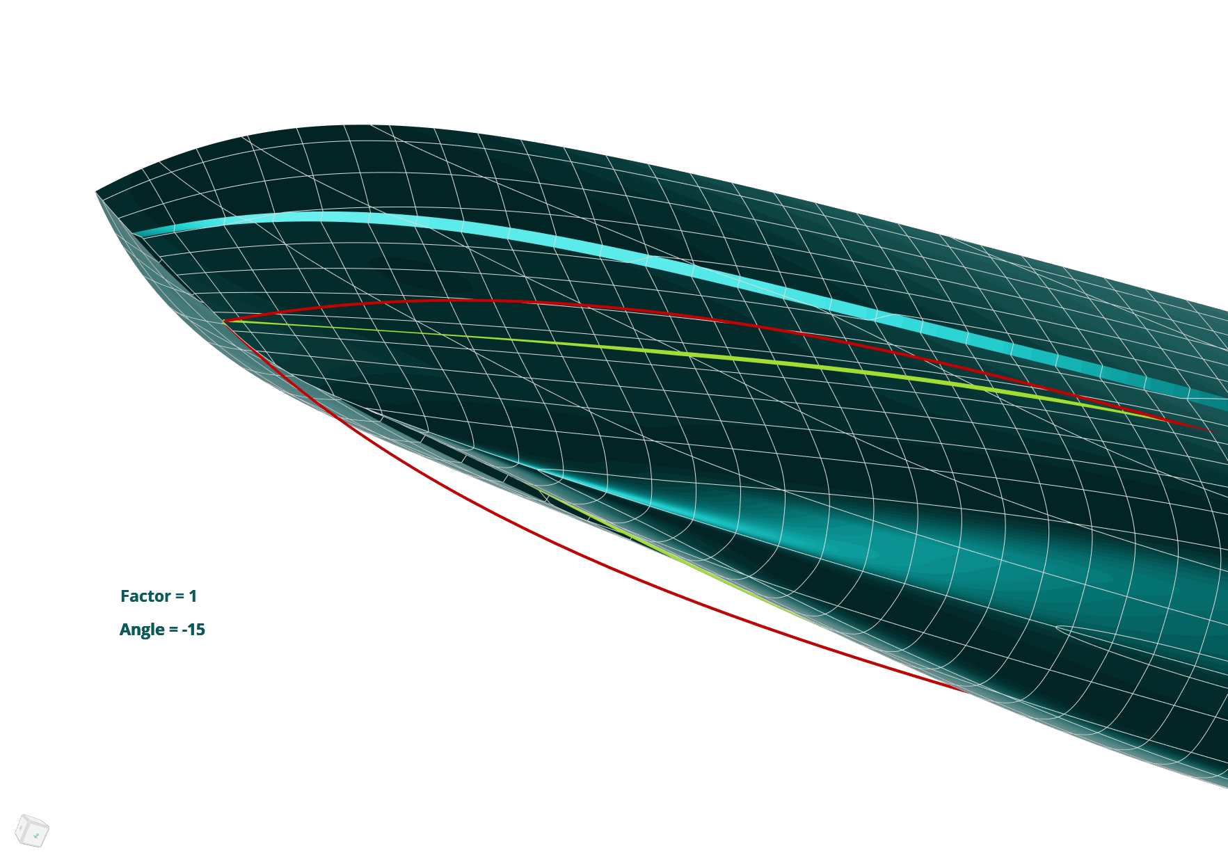
Once the deformation area is marked, the user needs to select a feature inside that area and specify how that feature is to be transformed. While these “source” and “target” features need to be supplied by the user, the deformation area will then be deformed by the algorithm in a way that ensures a tangent continuous transition between the target feature and the fixed area. Interpolation between the source and target geometry are also possible, as well as extrapolation.
Features that may be selected as source and target geometries are:
- A point inside the deformation area that will be translated to a target location,
- A collection of triangles that may be translated, rotated and scaled to a new location (discrete geometry only),
- A curve on the geometry that is mapped to a target curve somewhere in space,
- A sub-surface of the geometry that is mapped to a target surface in space (NURBS geometry only).
As the target geometries will be matched exactly, it is straight forward to accurately control the shape in a parametric way, especially when using one or more curves as source and target geometries. The translation of points and triangle sets with the dedicated handle tool, on the other hand, allow for an intuitive, quick and interactive modification of the geometry.

Learn More
1. Watch the webinar recording about morphing in CAESES® 5 for more details.
2. Download CAESES®, register for a trial license.
3. Test the morphing functionality yourself with the corresponding tutorials in CAESES®.
Questions?
Please do not hesitate to get in touch with us if you have questions in the context of your specific application. We look forward to discussing it together with you!