

 Intake ports are the final part of an engine’s air induction system. They connect the intake manifold with the combustion chamber and are opened and closed with the intake valves.
While intake ports are found in all types of engines, they have an especially pronounced influence on the air/fuel mixture formation in gasoline (SI) engines. In Diesel engines, the piston bowl also helps with that task.
Furthermore, the port shape is responsible for the charge motion, where favorably shaped vortices reduce energy dissipation, and it influences the amount of air that gets into the combustion chamber, where an increase leads to higher engine performance.
This blog post gives you a short introduction of the relevant intake port design capabilities within CAESES®. In addition, a recent project is outlined where CAESES® and STAR-CCM+ were coupled to fully automate the shape optimization of an intake port.
CAESES’ Intake Port Design Capabilities
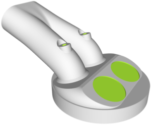
CAESES® has been effectively used to design state-of-the-art intake ports and brings along several key capabilities for this specific task. The main “duct” of the port is typically modeled using CAESES®’ Meta Surface technology, where a parameterized cross-section is swept in a specified direction, e.g., along a path, and function curves control how the cross-section parameters change during the sweep. Arbitrary cross-section parameterizations can be used, see the animations below in the section “Geometry Setup”. Read a detailed description of the intake port modeling capabilities here.
This controlled-sweep approach brings along a high amount of flexibility, while keeping the number of design parameters as low as possible, for a faster optimization.
Design comparison of different intake ports in CAESES
Here is a short summary of the important features when designing intake ports with CAESES®:
- The geometry parameterization can be set up so that flow-relevant parameters are directly controlled, e.g., the distribution of cross-sectional area along the path, even under consideration of blocking due to the valve guide or stem.
- Alternatively, morphing methods can be used to deform an existing – imported – geometry. This is faster, but less flexible and offering less direct control. The morphing can be applied to a NURBS surface geometry and be exported as IGES/STEP/etc., or to a discretized geometry such as meshes or tessellations.
- Robust variation of the port geometry is possible with no failed variants. As for other geometries, one of the most important targets of our software is 100% robust geometry variation, obtained by smart parameterization and dependency-based models.
- Arbitrary constraints can be built into the model or monitored. Typical examples are: manufacturing constraints such as drafting angles and minimal radii, or packaging constraints, where the distance to neighboring components/elements has to be maintained.
- The geometry can be exported in several different formats suitable for your CFD/meshing tools. Many of the formats support patch naming, so that the downstream tool can correctly identify surface patches for the assignment of individual mesh settings or boundary conditions.
Example Case:
Intake Port Optimization with STAR-CCM+
The following sections describe an optimization study that was carried out to demonstrate the workflow for intake port optimization using CAESES® and STAR-CCM+. The port was a typical geometry for an SI engine, combined with a pent-roof combustion chamber and four valves per cylinder.
Geometry Setup
The parametric intake port model was created in CAESES® and a set of seven parameters were selected for the optimization.
ELLIPSE FACTOR
The ellipse factor in two streamwise locations. This controls if the cross-section has a circular or rather elliptical shape.
Cross section shape change via ellipse factor
ECCENTRICITY
The eccentricity in two streamwise locations. This blends the cross-section shape from a circular/elliptical to a D-shaped one.
Cross section shape change via eccentricity parameter
INLET ANGLE
The inlet angle, i.e., the angle between the intake port’s path and the horizontal plane.
Change of intake port inlet angle
INLET HEIGHT
The inlet height is a typical standard dimension of intake ports.
Change of intake port inlet height
STRAIGHT LENGTH
The straight length at the inlet. This controls the shape of the path, when projected onto a horizontal plane, specifically for how long it is straight when coming from the inlet. It has a major influence on the septum length.
Change of intake port straight length
STAR-CCM+ Automation
STAR-CCM+ was coupled to CAESES® using the Software Connector. The geometry as displayed before, was complemented by a half-spherical plenum to model the inlet flow conditions and exported in a “colored” STEP format, which includes individual IDs for the identification of the different patches. The simulation was carried out in steady, “cold-flow” conditions, comparable to a real-life air flow bench.
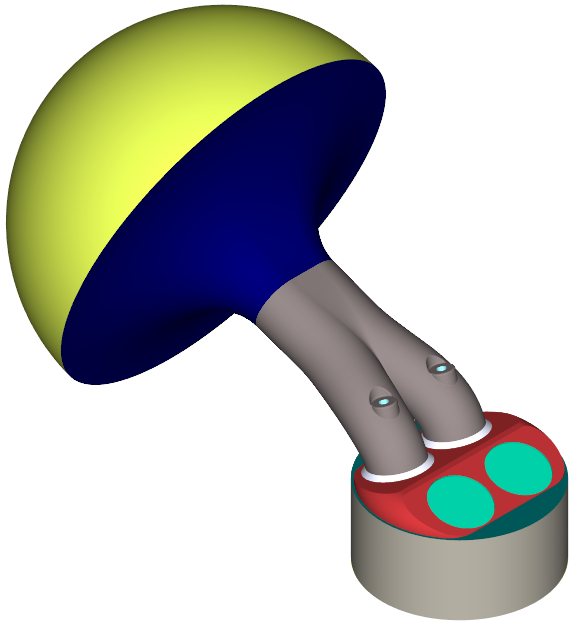
Colored patches for automated export of STL model
Optimization Process and Results
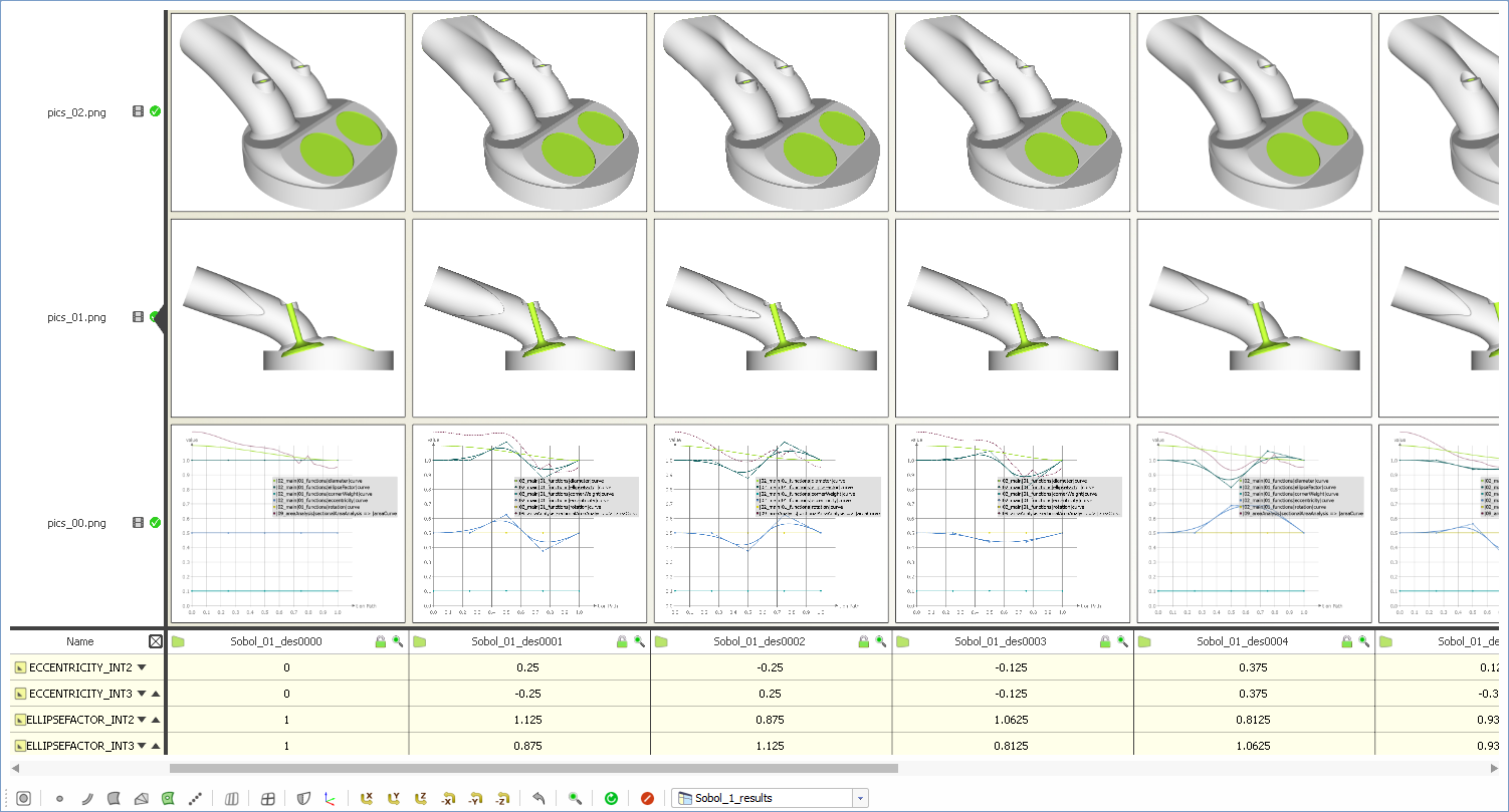
The intake port optimization was carried out in three steps. First, a DoE was run using a Sobol sequence to evaluate preliminary trends and correlations. Then, a preliminary optimization using a surrogate model and a multi-objective genetic algorithm was carried out to identify the Pareto frontier. These methods are fully integrated in CAESES®.
Finally, a second optimization run with the same method as before was executed, to further populate and refine the previously identified Pareto frontier. Two concurrent objectives were considered: the discharge coefficient, or port permeability, and the tumble ratio. Additionally, the turbulent kinetic energy in the spark plug region and the swirl motion (or omega tumble) were monitored. The whole optimization process comprised approximately 150 designs and therefore CFD simulations in total.
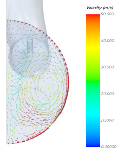
CFD results showing the flow velocity vectors for different – even extreme – designs (click for an animation)
The two objectives were – not surprisingly – anti-correlated and the influence of the design variables on the objectives was quite diverse. While, e.g., the cross-section eccentricity in the more upstream location had almost no influence, the same value more downstream had a pronounced, but opposite, effect on the two objectives. Other design variables were only correlated with one objective. E.g., the inlet angle had a positive correlation with the tumble ratio and the ellipse factor downstream had a negative correlation with the discharge coefficient.
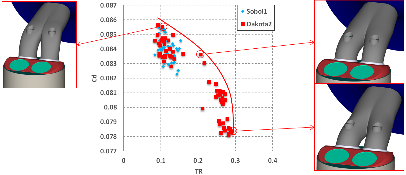
Selecting intake port designs from the Pareto Frontier
Several intake port designs could be chosen from the final Pareto frontier, depending on different considerations, whereby all the best solutions were characterized by a pretty high inlet angle and a rather short straight length at the inlet. The one design that was selected at the end exhibited a significantly improved discharge coefficient, with an only slightly lower tumble ratio as the baseline.
Download Tech Brief
A short summary of the CAESES® intake port design capabilities can be found in this tech brief (PDF).
More Information
If you want to hear this story in more detail, you can check out the recording of the webinar we ran jointly with R&D CFD. If you would like to discuss your intake or exhaust port applications with us, do not hesitate to get in touch! More information about similar applications can be found in our powertrain application section or the intake port design page.
Follow Us
If you are interested in CAESES® and in CFD-driven design optimization, then sign up for our newsletter. Don’t worry, we won’t bother you with too many emails. Of course, you can unsubscribe at any time 🙂
Awesome work. Very interesting.
Thanks Daniel!
This demonstration is exactly what I’m looking for, fantastic presentation, can’t wait act on what you’ve shown me today, TJ Johnson