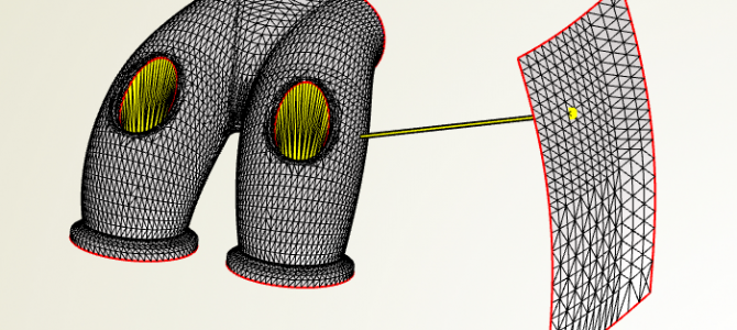
Some of our customers use CAESES® for shape optimization of existing geometries, we sometimes refer to it as a partially parametric approach. Typically, a geometry gets imported into CAESES®, using one of the various STL formats. The geometry is then deformed by a set of shift transformations or free form deformations. So far, this works excellent, considering the fact that free form deformations have been added to CAESES® just some months ago. However, in several situations we felt that there is still a lack of auxiliary functionality for which we needed a rather complicated workaround to realize the task. Finally, we came up with a set of new little things on our wishlist in order to make the design process easier. Here is a selection of the things that we have recently added to CAESES® – we’ll make it available in version 4.0.4:
Shortest Distance
We needed a way to set up constraints such as the shortest distance from one part to another, to keep track of a minimum distance when doing shape changes. An automotive example is the requirement of a part not to violate the installation space. Hence, our trimesh (that’s the object that contains the geometry triangulation) now offers a new command for calculating the shortest distance. In the following short video, we wrapped the command in a feature definition for better usability. With this, we’ve got the distance value for setting up a constraint, and the shortest connection is also visualized in the 3D view with a simple line object.
Open Edges as Curve
Open edges of imported STL data are now directly available as a 3D curve. We wanted to have this for the purpose of setting up the bspline boxes of free form deformations, where bspline boxes surround the geometry region that gets changed during an optimization. As one option, any 3D curve can be used as path to generate such a box, i.e. the box creation can be understood as a simple sweep along the 3D path. For STL data, we can now simply grab one of the open edges and use it as an input path for the bspline box. Without this little piece of functionality, we’ve had to set up such a 3D curve manually, this was really a boring task. So now it’s just there! The following video shows an imported STL geometry from which an open edge is directly taken as input path for a bspline box:
Split By Angle
This is another wish that immediately comes up if you cope with STL data in a CAE-software: A simple way to split the given data into several pieces, based on a user-defined angle. This allows users to receive the inlet and outlet patches separately, for instance. These patches can then be individually colored and used as input for the CFD meshing process. It also makes life much easier for our free form deformations because you can better select the individual parts that you want to deform, and e.g. switch off the visibility for untouched parts etc. Applying deformations only to a subset also speeds up the deformation process because of less input data. To sum it up, there are several benefits of this rather basic split functionality, so let’s simply add it to CAESES®:
Interested in trying out CAESES® for your application? Then check out our product pages for all amazing details. Note that we also offer a powerful & free edition of CAESES®, which can be downloaded from our website. There are no annoying or hidden limitations, and you can directly start to set up your own intelligent model today! Let’s go – give it a try 😉

