
CAESES 4 Video Tutorials
This is the archive for video tutorials related to CAESES 4. If you are looking for new video tutorials covering CAESES 5, please visit our new video channel.
 Lesson 1: Getting Started
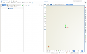
This should be your starting point. Learn about the graphical user interface, the visibility of objects, drag & drop mechanisms and so forth. We noticed that many beginners had problems with e.g. the object visibility (“Hey, where is my curve again, I cannot see it …”), which is the reason for setting up this initial lesson here. Please take the time to go through these 2-minutes videos, this is an important prerequisite to be successful with CAESES®. Enjoy!
How to start with the graphical user interface
How to work with visibility and filters
How to link objects for parametric relationships
 Lesson 2: Basics of Geometry Modeling
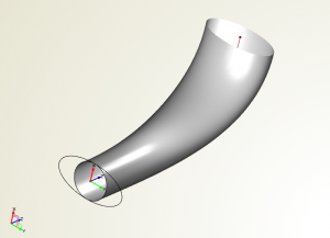
Learn about the basic concepts of simple geometry modeling in CAESES®. When you compare it to other CAD tools in the market, CAESES® is a bit different. However, we have a purpose for treating things different: our ultimate goal, the automation process! For this, we need to make sure that dependencies are correct all the time when changing geometry. And, we have to ensure that geometry changes are 100% robust. As a result, we have created an object-based workflow for you in CAESES®: You can create objects that consist of attributes and properties as well as functions which you can use. This concept is always present i.e. also in the way we create geometry in CAESES®. Check out this lesson to get a better understanding of this innovative modeling process. We keep the videos very simple to show you the basic ideas, but everything is valid for any complex modeling task, and the presented basics (creation, settings, etc) can be directly applied to any curve or surface object.
How to create a smooth curve (fspline)
How to create a simple sweep surface
How to use curve ends and surface edges
How to use an intersection point
 Lesson 3: Preprocessing Capabilities
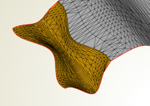
CAESES® provides easy-to-use functionality for the generation of clean and user-defined STL data. The central object for this is the “trimesh”. You can input a list of surfaces (or trimeshes) and it creates a surface triangulation. In addition, you can make use of some surface healing features, such as snapping and joining of patches. Everything is controlled by user-defined tolerances. Once you’ve set up a trimesh, it can be re-used for all new design candidates, e.g. when running automated studies and optimizations. This is useful for anyone who needs STL data.
Note that breps (see lesson 6) also generate perfect STLs – in case all of your surfaces are given as mathematically clean and neat data.
How to create a closed surface mesh (trimesh)
 Lesson 4: Feature Definitions
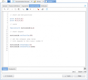
Feature Definitions (FD) allow you to wrap complex functionality in a single object. With this, you can re-use your functionality in other projects again. And you can keep your project structure much cleaner since many objects are “hidden” within a single object, the “feature”. FD are objects with user-defined input, a command sequence and some output. Actually, this is pretty much like a function or method that holds a code snippet, and processes the user input. FD can be a used to wrap custom curve definitions for advanced surface modeling (we need FDs in the context of meta surface modeling), but it can also wrap proprietary import or export routines (file I/O, e.g. import ASCII data). The FD is the template which holds the logic, while the “feature” is an instance of a specific FD. Features are an amazing and central piece of CAESES®.
How to define input arguments of a feature
How to set the attributes of a feature
How to create a feature definition from selection
How to define a loop in a feature definition
How to debug a feature definition
 Lesson 5: Advanced Surface Modeling
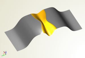
This is one of the most interesting parts when using CAESES®: meta surfaces! There are no limits, you can realize almost any surface idea to generate a smarter model with full control using function graphs. First, you have to define a curve within a feature definition (see lesson 3). For the input parameters of this curve, you can then define distributions i.e. function graphs. Another CAESES® object puts everything together: the curve engine. It connects the curve definition with the parameter distributions. As a result, this curve engine can generate a bunch of curves. This information is finally used by the meta surface object. From our experience, it takes a bit to fully understand this concept. But once you’ve got it, you will start smiling!
How to use the scaling factor of curve engines
How to use the skinning of meta surfaces
 Lesson 6: Solid Modeling
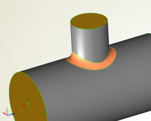
The “brep” type in CAESES® extends the geometry functionality with solid modeling capabilities. Breps allow you to create solid geometries. You can apply Boolean Operations between two given solids, extrude faces, and you can inscribe fillet surfaces. In CAESES®, the colors of the faces play an important role as well. You can assign different colors to different faces, which is beneficial for e.g. colored STL exports (exporting different geometry groups for easier meshing and grid generation control). Colors are also unique identifiers for the specialized fillet generation process in CAESES® and this keeps the geometry creation 100% robust for all design candidates.
When you cope with surfaces and breps that are modeled in a clean and neat way, the STL data will be perfect. However, in some situations you can also use the trimesh object: It creates a surface triangulation and comes with some healing functionality, such as joining and snapping mechanisms. Check out this video from the preprocessing lesson above.
How to create a solid from intersections
How to prepare a brep for STL export
 Lesson 7: Software Connection
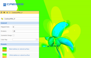
CAESES® allows you to integrate external software. In most situations, this is some kind of simulation tool (e.g. CFD), but basically any tool that comes with a batch mode can be integrated into CAESES®. The “software connector” is the main widget that helps you with this task. You define the geometry and its export format, the control files for your tool, as well as the result data. With this, you can control your tool from within the user interface of CAESES®. Result values can be used to define objective functions. And, you can even load 3D flow data into CAESES®, for interactive post-processing.
How to connect an external software

Lesson 8: Variant Creation
CAESES® allows you to create new design candidates of your geometry model, including corresponding CFD results. You can generate new design manually, which is shown in the following first video, or fully automated. CAESES® takes care of the variant geometry and its result data management so that no scripting etc. is required.
How to create a manual variant