

We are excited to announce the new CAESES® 4.4 release, which can now be downloaded from our website. Based on the great input and feature requests from our users and partners, the functionality and the resulting benefits are constantly growing. This new version comes with more than 30 new major features and a new help system, while at the same time a large set of reported bugs and issues has been resolved. Some of the version highlights are given below, feel free to get in touch with us if you have any questions or comments!
Update Dec 6, 2019: Version 4.4.1 is already out now!
New Help Portal
With CAESES® 4.4, we added a first version of a new help portal, to make all essentials available that you need to use CAESES®. You can find it in the documentation browser. The motivation for this new help is to centralize all documentation in one place, and to make things easier to find for you. The new help also provides a first set of useful snippets for feature definitions that can be copied and pasted into your own definitions. We will continue to add content in the future (tell us what is missing!), and we look forward to receiving your general feedback on it.
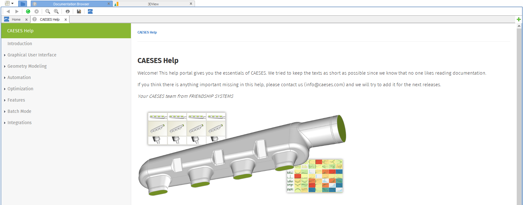
New help portal in CAESES 4.4
Robust Variant Creation of Complex Geometries
The entire geometry engine of CAESES® has been improved to provide faster and more robust geometry operations. Based on test cases from our customers, the algorithms for Boolean Operations and filleting have been further developed. This effort continues to ensure that the geometries of complex models do not break or fail to regenerate within automated design studies.
Robust Boolean Operations and filleting for complex geometries
Efficient Rendering of Larger Models
The rendering and navigation (zoom, rotation, translation) in the 3D view have been accelerated. So far, models with a large amount of data (e.g. from imported data or complex parametric models) showed a slow response in the 3D view. By using a completely new approach to render and visualize the data, this behavior is now substantially improved so that working with huge amounts of data is more fun again.
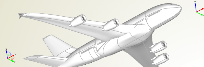
Faster rendering and smoother navigation of larger models
Selection and Transparency
When selecting an object (e.g. point, curve, surface, BRep) in the tree or in the 3D view, all other objects are now set to transparent. As a result, it is much easier to detect which object was selected. In addition, it is also easier to investigate the selected geometry because it is no longer hidden behind other non-selected objects.
Transparent visualization of non-selected geometries
Patch Pre-Processing
This is a new feature which will really excite users that need STL output: Individual patch settings for BReps as a one-time pre-processing step for all variants. Users can override the global settings for the color and the triangulation. Just choose the edit mode of the BRep, select a patch and apply your individual settings. All these settings are propagated down to the exported STL file. This means that even subsequent operations (add sources, trimming, intersections, etc.) will maintain these settings. You can still use global tolerances e.g. for the triangulation accuracy and the colors, but your individual local setting will still be there. As a result, you have more control and you can have a higher accuracy for critical, highly curved regions while not substantially increasing the total amount of data.
Video
Find more details on the Simulation-Ready Geometry page, including a video that demonstrates this new functionality.
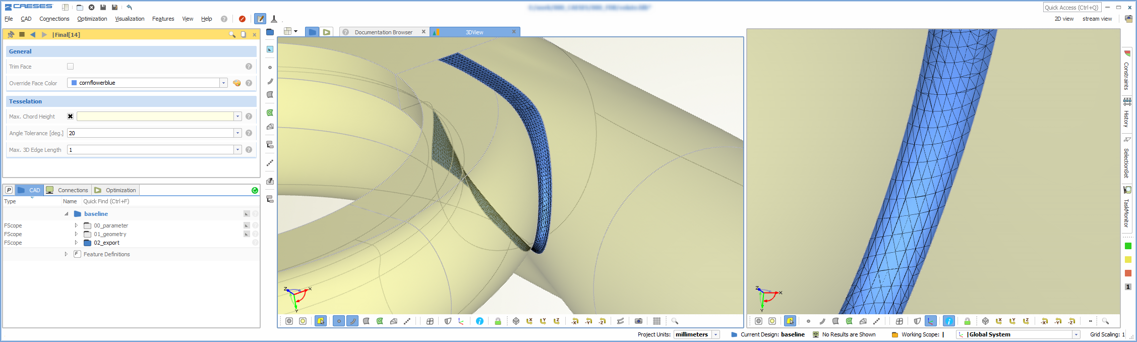
Assign color and triangulation settings for each individual surface patch
BRep Healing
Some new healing options are now part of the BRep add sources operation. These healing options can fix the topology of “unclean” BReps by internally applying snapping mechanisms. “Unclean” means that corners or edges of adjacent geometry patches do not coincide exactly even though it looks like they are matching, as long as you do not zoom into the details. Such numerical artifacts have been observed in imported files from other CAD systems. In particular, and as a request from our maritime customers, the new healing capabilities work well for ship hull geometries that are exported by the NAPA software. See also this blog post about flow domains for NAPA geometries for some more information.
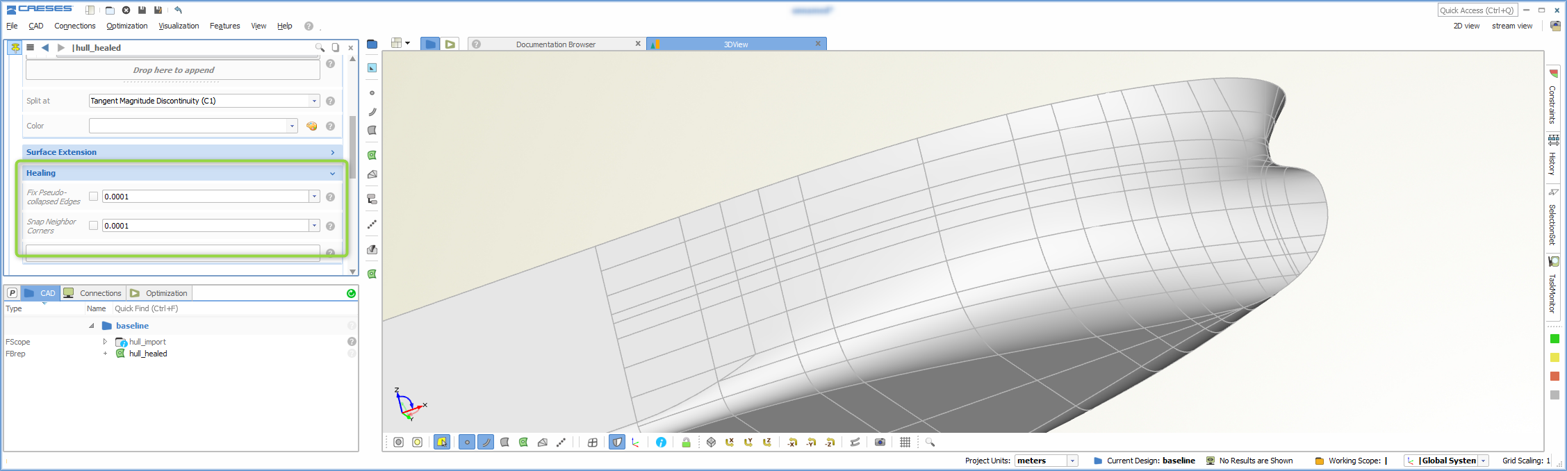
New healing options to automatically repair imported geometries on a NURBS basis
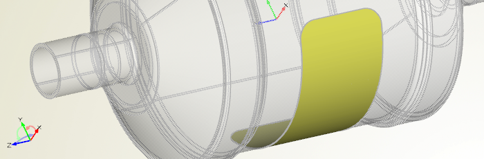
Automated Mesh Deformation
The process automation has been extended to let users work with ANSYS Fluent meshes. These *.msh files are now supported in the software connector, and they can be imported and used for shape optimization by applying the Free-Form Deformation or other shift transformations of CAESES®. The software connector offers a new possibility to choose a Data Connection whose deformed data will be automatically exported in an optimization loop. Besides the Fluent mesh file format, the open-source format *.vtk (The Visualization Toolkit) is also supported in CAESES® 4.4. More formats are on their way!
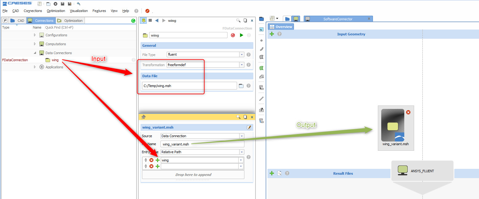
The CAESES software connector supports the import and automated deformation of ANSYS Fluent volume meshes
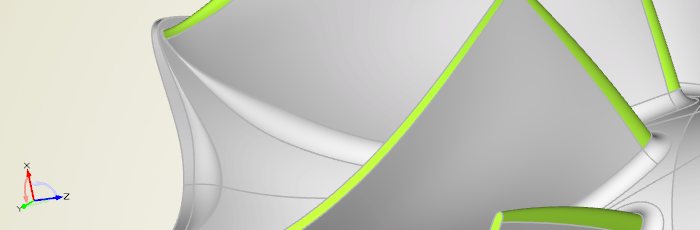
New Surface Features
With version 4.4, you can now consider derivative information from the adjacent surfaces when creating a Coons Patch or a Lofted Surface. When creating a Coons Patch, you need to provide surface curves such as the surface edges from the 4 outer surfaces. The Coons Patch automatically computes the derivatives based on this input and generates a smooth transition to these surfaces.
In the context of Lofted Surfaces (i.e. skinning cross-section curves), derivative information can be included at the start and end cross section to further control the transition and the shape of the lofted surface. This information is collected from two adjacent input surfaces that are now additional input properties. This new capability can be combined with the use of rail curves as further control for the surface generation process.

Create a smooth patch with derivative information from adjacent surfaces
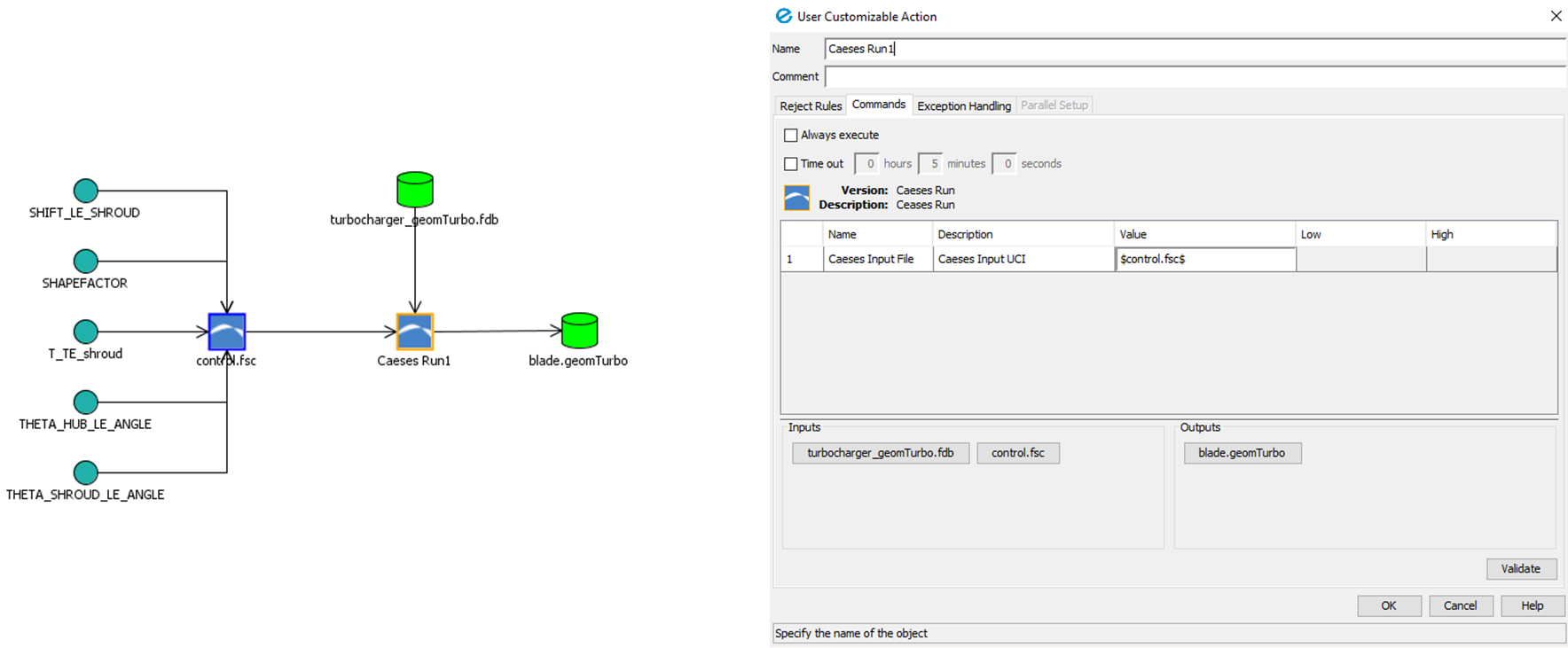
Expressions in the FSC File
All dependencies and expressions can be written into the fsc-file that is used for the batch mode run of CAESES®. With this, users can run and control a CAESES® project without using the graphical user interface at all. This is handy for making some very quick changes to the project without starting up the user interface. In order to write these parameters into the fsc-file, activate the new option under projects > exports > exportFSC.
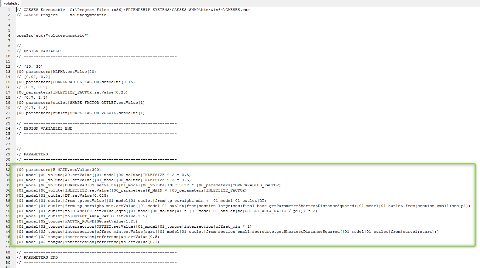
Besides design variables, you can now also control expressions within fsc-files
Improved Usability
Based on the wishes from our users that we regularly receive, e.g. through the helpdesk and the forum, we have added several nice-to-have features such as convenient geometry creator commands and new GUI widgets. For instance, since setting colors for surfaces is such an essential task in CAESES® (to prepare them for automated meshing with fixed IDs), a missing color picker tool was added to the color object:
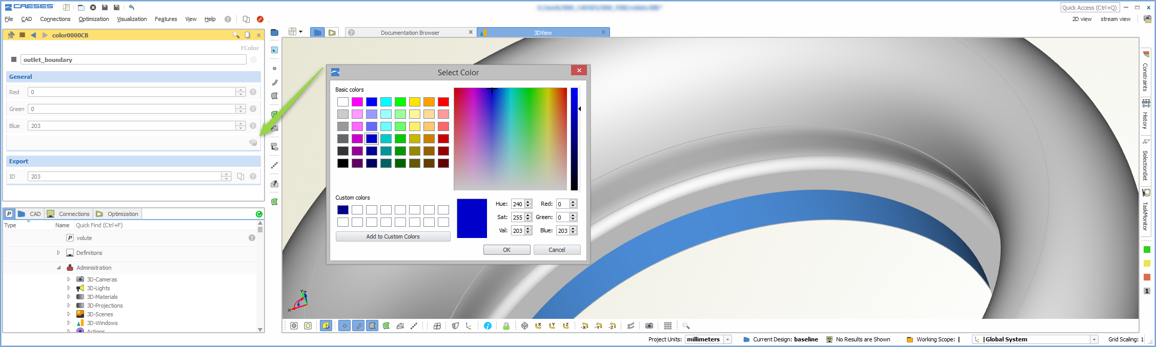
New color picking possibility for assigning patch IDs
Faster Access to Display Options
Some of the frequently used display options now have a separate icon for faster access. This includes displaying the control net of the underlying NURBS representation for curves, surfaces and BReps as well as visualization of BRep edges (open edges vs. all edges using a red/green color). There is also the new option to show the edges of a BRep in a grey color, which gives you a cleaner view if you do not need the edge checks or if you want to create screenshots.
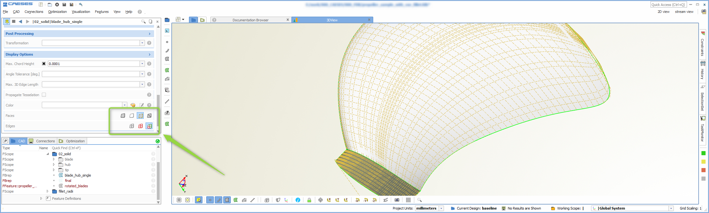
Just a single click for frequently used display options
Update of the ANSYS App
The CAESES® geometry engine (to integrate CAESES® into the ANSYS Workbench) has been updated where a major feature could be added. In the previous version, the surface colors were transferred with their color codes, i.e., the color codes appeared as the Named Selections. In this new version, the name that you set in CAESES® finally shows up in the user interface of the ANSYS Workbench. For instance, if you tagged one of your surfaces as “io_inlet” (through creating a color with this name), this name will appear again as the Named Selection. In addition, you can also manipulate the geometry in the ANSYS DesignModeler, and the automation will still work which was not possible with the previous CAESES® app.
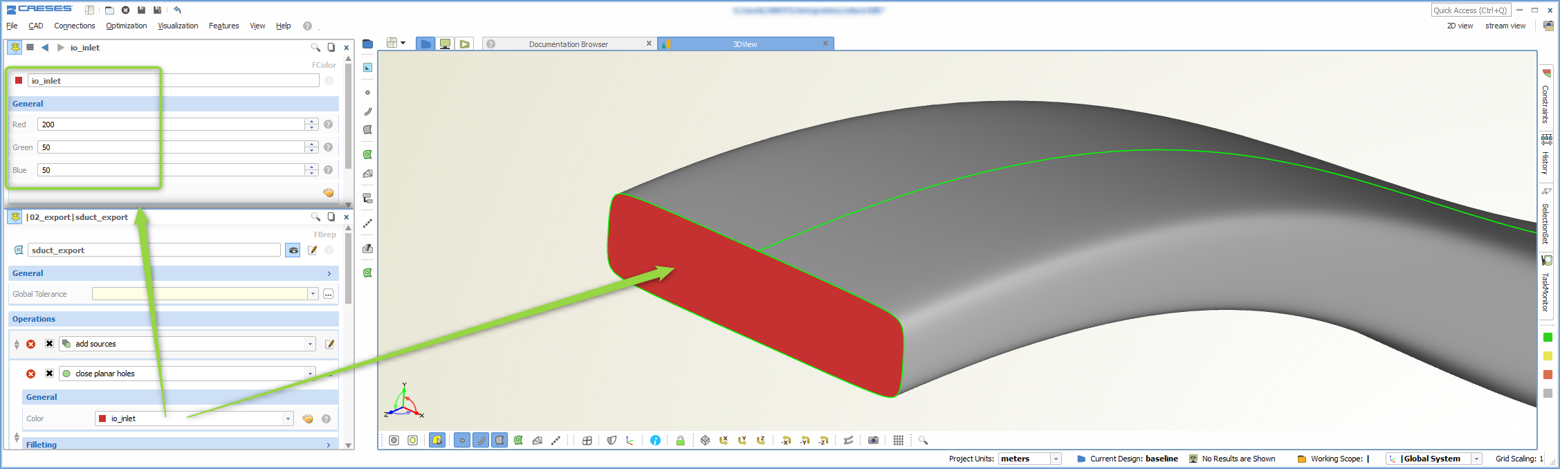
Assign colors in CAESES with specific names to prepare the ANSYS “Named Selections”
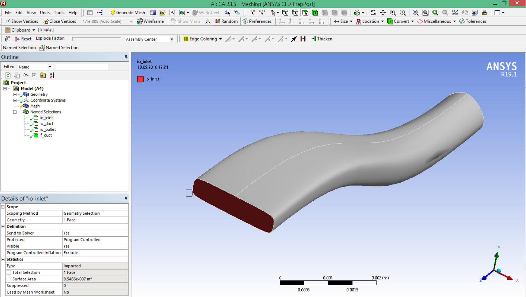
Color identifiers will be automatically transferred as “Named Selections” to the ANSYS mesher and the ANSYS DesignModeler
CAESES TurboGrid Engine
Another highlight in the context of our collaboration with ANSYS is the beta release of the CAESES® TurboGrid Engine App. This new ANSYS app allows you to use your parametric CAESES® blade model within the ANSYS Workbench for automated meshing with ANSYS TurboGrid. There is a short tutorial in the documentation browser that explains how it works. The new integration is highly streamlined so that it takes only a couple of clicks to automate the blade design process!

CAESES 4.4 ships a new beta app to automate the meshing of CAESES blade models with ANSYS TurboGrid
Optimus Integration
The connection between CAESES® and the Noesis software solution Optimus has been further improved to integrate CAESES® into the user interface of Optimus. All you need for Optimus is the fsc-file for the batch mode run of CAESES®, and Optimus will show all design variables along with their lower and upper bounds. Simply drag & drop the CAESES® icon within the Optimus user interface into the Optimus work space to integrate, configure and run CAESES®. More details are coming up soon!
Easy-to-use CAESES integration in Optimus
Changes Log and Download
All details of the new version can be found in our changes log. If you observe any issues or problems, please get in touch with us through the helpdesk.
Follow Us
If you are interested in updates about CAESES®, then sign up for our newsletter. Don’t worry, we won’t bother you with too many emails. Of course, you can unsubscribe at any time 🙂