Hi together,
This post gives you a very quick overview of connecting OpenFOAM® to CAESES® for the purpose of CFD automation. In general, connecting an external software to CAESES® only takes a few minutes, and with this you can immediately conduct design explorations and shape optimizations.
For more information, check out the tutorials and example projects that are included in CAESES® and CAESES® Free. The forum also contains a lot of OpenFOAM® related posts that might help you to get started with it.
There We Go: An Example
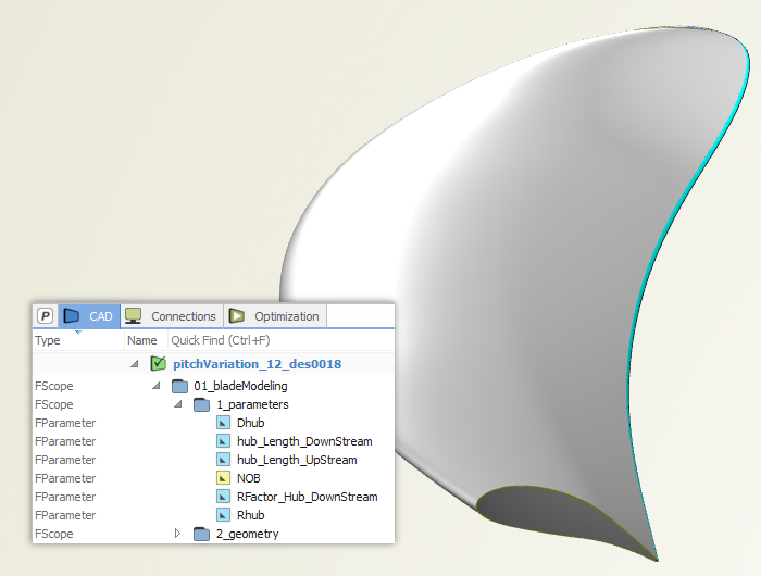
Let’s consider a simple design study of a propeller where the parametric blade geometry has been modeled in CAESES®. You can change the diameter and the number of blades, and you can actually modify the shape through radial functions for the 2D profile parameters (thickness, chord length, camber,…).
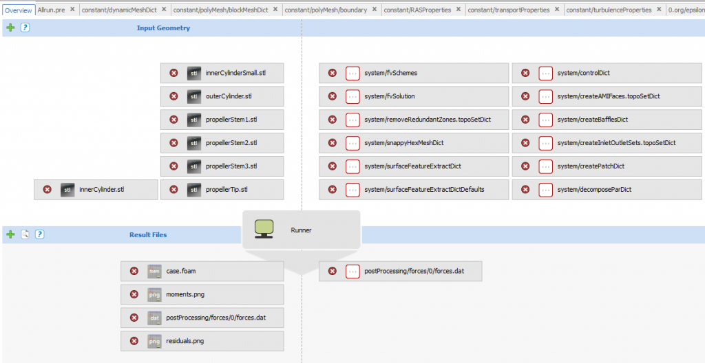
Software Connector
As soon as the geometry model is ready, a new software connector is created in CAESES®. First of all, you need to specify the input geometry, i.e. the blade patches given as colored STL data. Just drag & drop the blade into the connector. Secondly, provide the script files (allrun.pre, dicts, …) of your OpenFOAM® setup. Since you also want to see some CFD results in CAESES®, finally add the result files to the connector that get written by OpenFOAM® or by additional tools such as GnuPlot. Examples are table data, *.foam and *.png files.
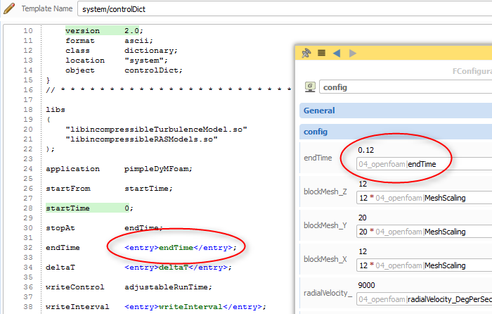
Full Control
The script files can also be parameterized to change the values in these files. You need to create an entry in your script file as well as a parameter in your CAESES® project. With parameters, you can nicely control OpenFOAM® through the CAESES® GUI. The values of the parameters are automatically replaced in the script file as soon as the software connector i.e. the computation gets triggered. Note that this allows you to conduct not only geometry studies, but also simple parameter studies of your setup. CAESES® automatically parses ASCII files and highlights numbers for quick creation of such entries.
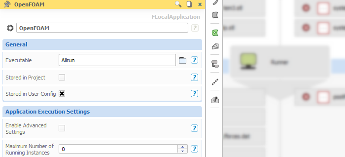
Executable
We still need to tell CAESES® about the executable file. In our example, the “Allrun” script is just another input script that gets automatically copied into the current design directory. From there, it will be triggered later on. Create a local application and set the “Allrun” script as executable. Ready!
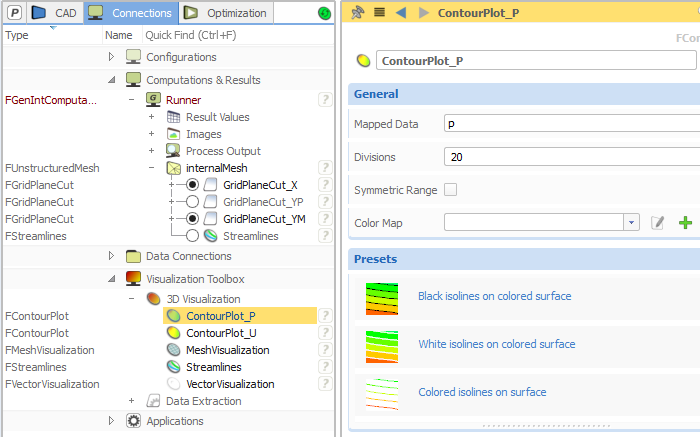
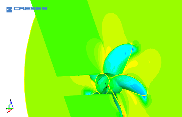
Results and Post-Processing
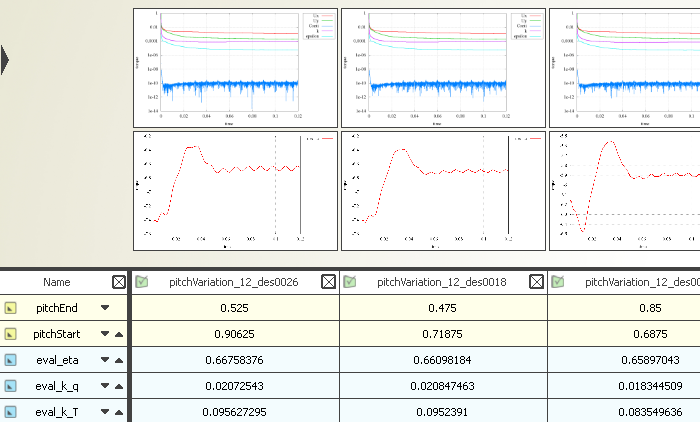
Now you can run an automated design study using a design engine (LHS, Sobol,…). As soon as CAESES® has finished this run, you can take a look at the result files and browse through the variants. This is the fun part because the entire variant management happens in the same GUI! CAESES® comes with post-processing functionality to create grid plane cuts, streamlines, contour plots and much more. In addition, you can use the design viewer to compare the different design candidates side-by-side. With version 4.0 of CAESES®, not only geometry variants and screenshots can be compared, but also external *.png-files are automatically loaded into the design viewer (see last screenshot).