Aerodynamic Shape Optimization: A Practical Guide
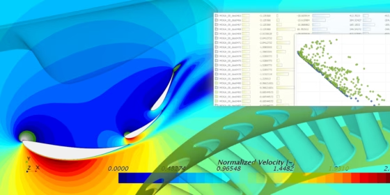
When it comes to fluid- or aerodynamic shape optimization, we have been talking a lot about very specific applications in our recent blog posts, such as the design of race car rear wings or the shape optimization of turbine blades. Simulation engineers from the aerospace, automotive or turbomachinery sector are interested in finding optimal designs with superior performance but also with a high robustness in terms of operating points. They investigate quantities such as lift and drag coefficients, vortex structures, pressure, shear stress and velocity distributions, and try to improve the flow and structural characteristics of their products. Thanks to the affordable hardware resources, engineers can now scale their design process with a few clicks to explore hundreds or even thousands of design variants.
This article now focuses on giving you a rather quick and practical guide to shape optimization with CFD (Computational Fluid Dynamics) and other simulation tools. We’ll look into requirements for the geometry models, the meshing and simulation setup, but also at optimization strategies and distributing simulations on HPC systems.
Parametric Models for Aerodynamic Shape Optimization
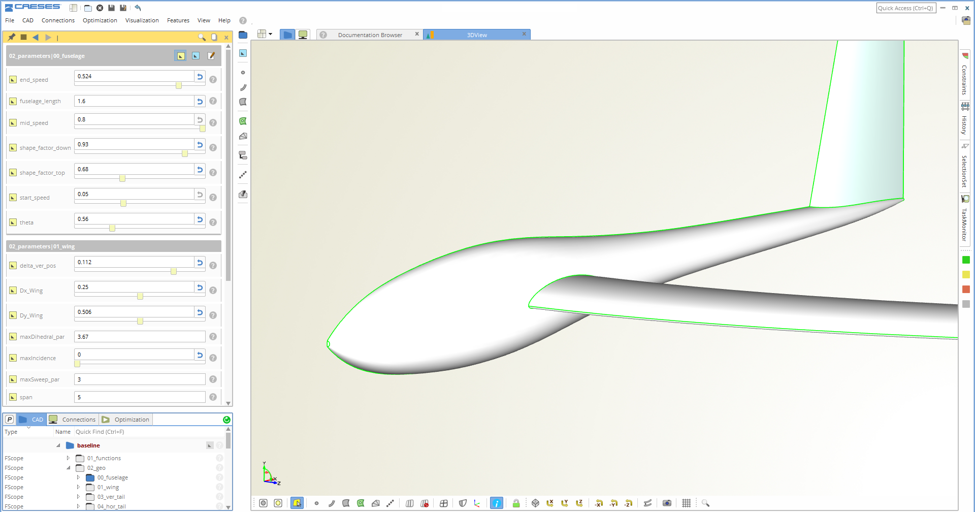
In many organizations, the existing CAD models of their products (e.g. aircraft bodies and wings, turbines, car components, etc.) are typically parametric. However, when it comes to variable geometry that needs to be robust and ready for an optimization loop, many of the traditional CAD systems fail at some stage. The regeneration of geometry sometimes unexpectedly breaks or returns an error. The reason could be as an example a failing intersection or filleting process. This is only one bottleneck. If you have to automatically create a mesh for new design candidates, all face IDs (e.g. colors with names) need to be the same for each design because the IDs are often referenced in meshing tools.
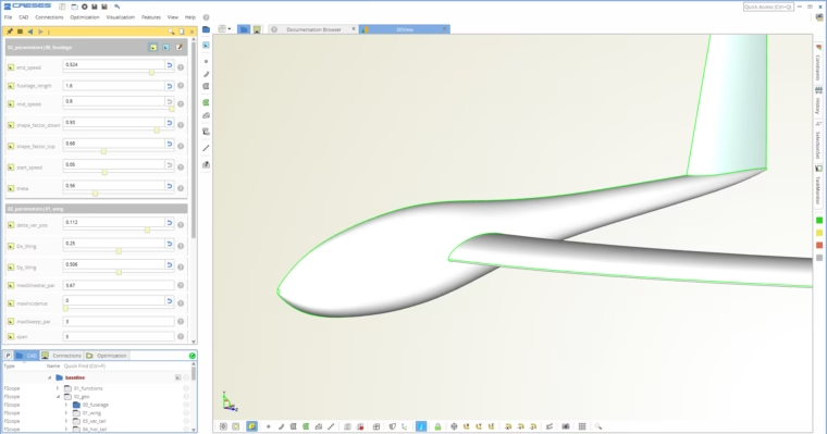
Robust parametric CAD models for automated aerodynamic shape optimization, created in CAESES
So, the first thing you need is a parametric model of your product that is ready for automation. If you have to pick a CAD software or geometry modeler, you should ideally consider the following issues:
Dedicated to Automation
Make sure you use flexible parametric technologies and tools that are geared towards automation. Note that some of the CAD tools on the market were initially not made for this task or do not target such a design process at all.
Robustness
Your geometry should be 100% robust, i.e., the regeneration of new geometry candidates should never break or fail.
Innovation
As an aerodynamic engineer, you should be able to quickly build innovative new ideas into your geometry model (e.g. flow-related features), either together with the CAD department or on your own. This is important especially for the long-term competitiveness of your product.
Parameter Reduction
Your CAD tool should give you smart techniques for parameter reduction, to minimize the overall simulation time in the optimization. This can be either smart parametric modeling techniques or integrated methodologies such as PCA (Principal Component Analysis), etc.
Identifiers
The face IDs and names are preserved for all generated designs to automate the meshing and simulation. This is required e.g. for some meshing tools, in order to be able to run a recorded script.
Constraints
The geometry constraints are automatically satisfied for each design. This includes cross-section areas, thicknesses, and minimum distances (packaging), etc. For these tasks, your CAD tool needs to offer integrated optimization methods that can be used for defining geometry.
Automated Pre-Processing
Finally, a few CAE tools expect good-quality STL geometry so you need some controls for the exported surface mesh quality.
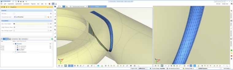
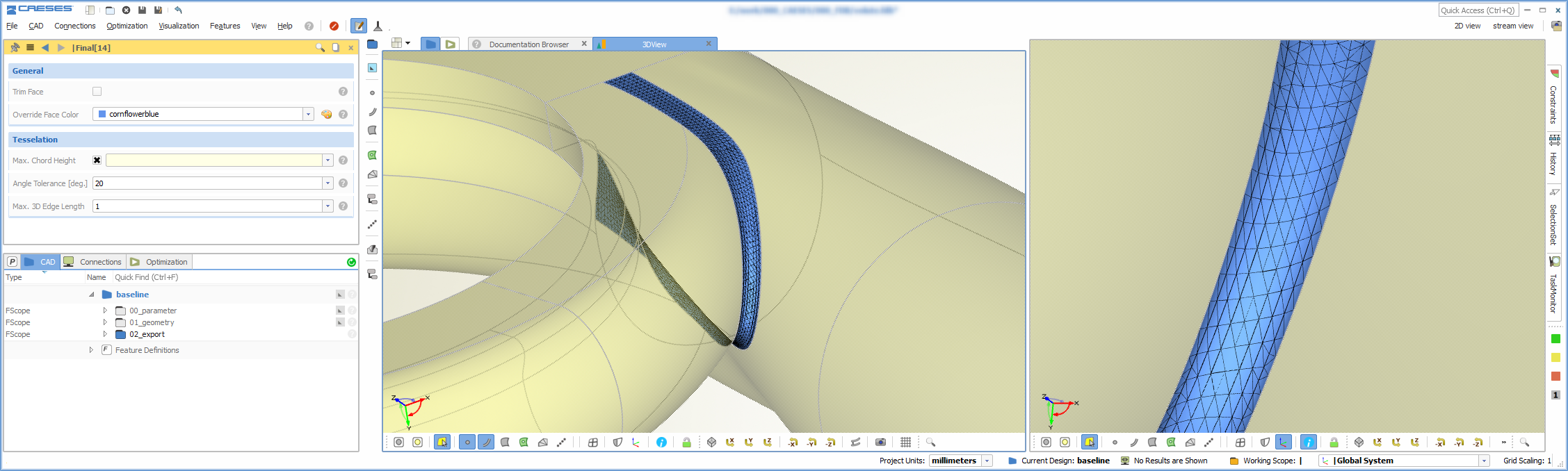
Assign color and triangulation settings for each individual surface patch
Automate Meshing and Simulation
Once you have the geometry ready for automation, you need to decide on your meshing and simulation strategy. Probably, you have your simulation setups already, and you simply need to automate it.
In some cases, the first phase of design explorations can be conducted with simpler simulation approaches, e.g., potential flow codes or other preliminary evaluation tools. These calculations are much faster than full-blown RANS (Reynolds-averaged Navier-Stokes) codes and help you to find a promising direction. You need to make sure that your “simple” solution really gives you the information you need, within the quality range that you require for the exploration phase, and based on your experience as a simulation engineer.
No matter which approach or software you choose: All these simulation tools need to be automated, and this is increasingly easy for most of the solutions in the market. Usually, they run in batch mode as well. You have to do the recording beforehand, i.e., some kind of scripting, which replaces the baseline geometry with the new design candidate. Examples of meshing and simulation tools that can be automated are ANSYS software, STAR-CCM+, NUMECA tools, TCFD, GridPro, POINTWISE, etc.
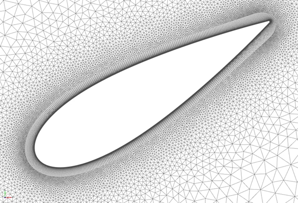
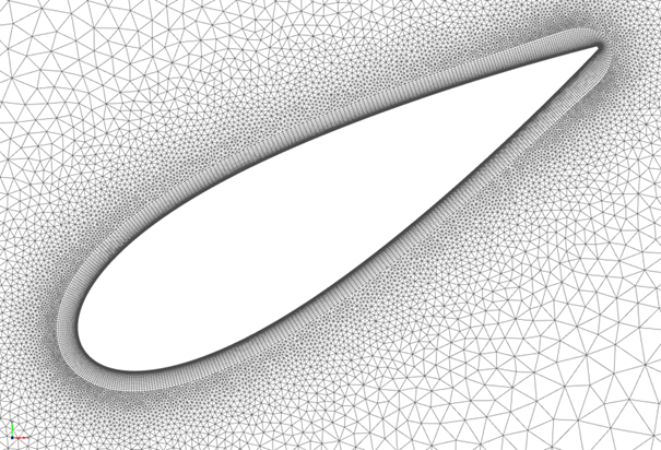
Example of a vertical wind axis turbine (2D cut of the blade): Fully automate the meshing, to have no manual interaction for generated design candidates
Adjoint CFD
Besides potential flow codes and standard RANS solutions, there is also adjoint CFD which gets more traction in engineering applications. Tools such as CAESES can also link the parametric model to the adjoint CFD solution in order to find the most important geometry parameters for your optimization. Automating adjoint CFD is pretty straightforward as well. In most cases just an additional result file needs to be taken into account.
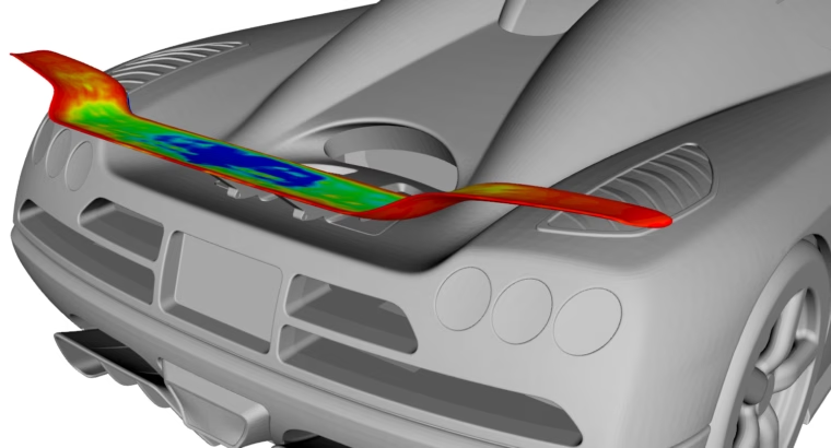
Results of adjoint CFD computations, used for shape optimization
Structural Analysis
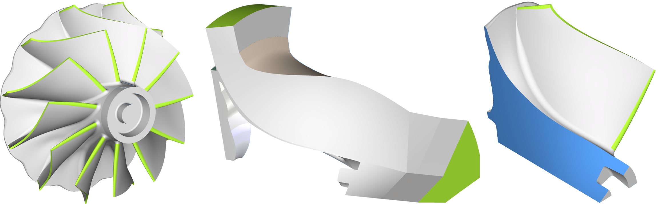
If you are not just considering the flow characteristics of your component, but also the structural behavior, you need to integrate these additional computations as well (here is a turbomachinery example). Since these tools have different requirements, it might take some time to integrate it into the full loop. But you will win a lot if you manage to finally go the holistic track. From our experience, organizations can save up to several months of engineering time only if the CFD and the structural departments tightly collaborate within shape optimization tasks.
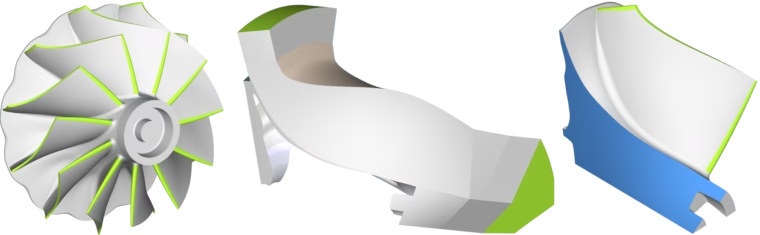
Geometry model of a turbine that automatically comes with the parametric domains for CFD and structural analysis
Choosing the Right Optimization Strategy
Most of the engineering applications today are pretty expensive when it comes to the overall simulation time of a single design candidate. Hence, you need an efficient optimization strategy to accelerate the design process, and to find your optimal design in shortest time. Here is one recommended strategy for typical fluid or aerodynamic shape optimization tasks:
Sensitivity Analysis
Depending on your simulation time, conduct a design exploration phase with a set of samples where you learn about your optimization problem. Which of the free variables are important, and which of them can be deactivated for the next phase of the optimization? Check the correlations and understand what’s going on. Your expertise counts in this phase! As an example, let’s say we create and analyze 100 different designs.
Global Optimization
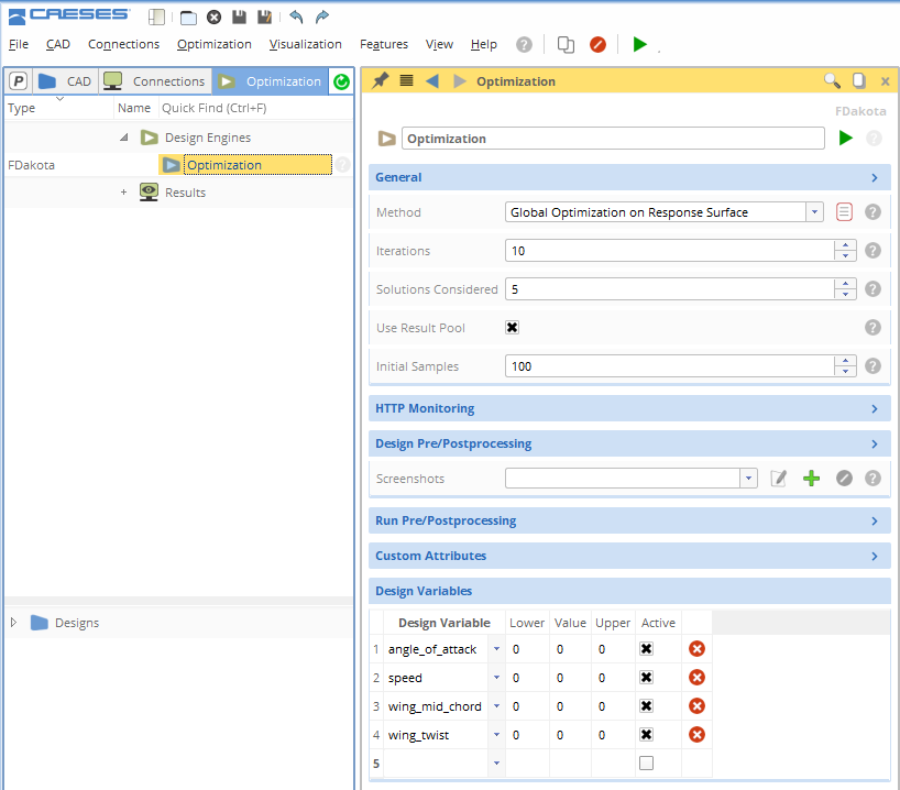
Run a global optimization based on the data collected in the sensitivity analysis. Create a response surface model where you recycle e.g. the 100 designs, and run a genetic algorithm on this surrogate. This can be fully automated, and you can decide how many iterations you want to run, depending on your hardware and license resources. The surrogate models are often generated on the basis of either Neural Network concepts, Radial Basis Functions, Kriging, or just simple polynomial functions.
Local Optimization
In some situations, and if there is still some time left, it can be beneficial to take the best design(s) from the global optimization and run a few more iterations by using a local search. In most industry-relevant cases, derivative-free methods are recommended and do a good job in fine-tuning your designs.
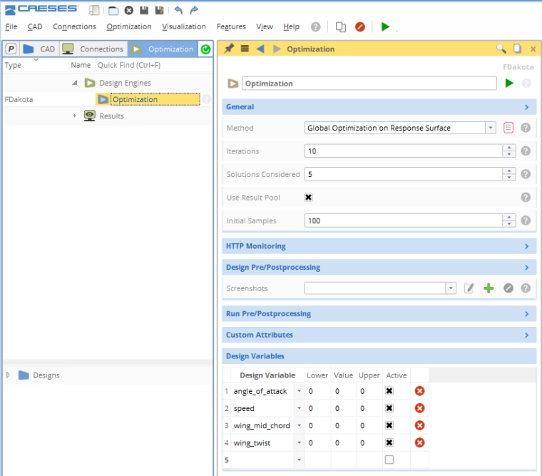
For many optimization tasks, response surfaces models can be used
For more information about surrogate models, see the article “Global optimization using response surfaces”. Of course, there are many other strategies possible: For instance, run the sensitivity analysis as explained above and then directly apply a local optimization to a few promising design candidates (using the reduced parameter set). Finally, some of the optimization tools in the market offer one-click optimization strategies where a combination of the methods from above are coupled. And since AI (Artificial Intelligence) and machine learning are a big movement, we will also see new optimization solutions coming up in the market that introduce innovative approaches to aerodynamic shape optimization.
Make Use of HPC Clusters
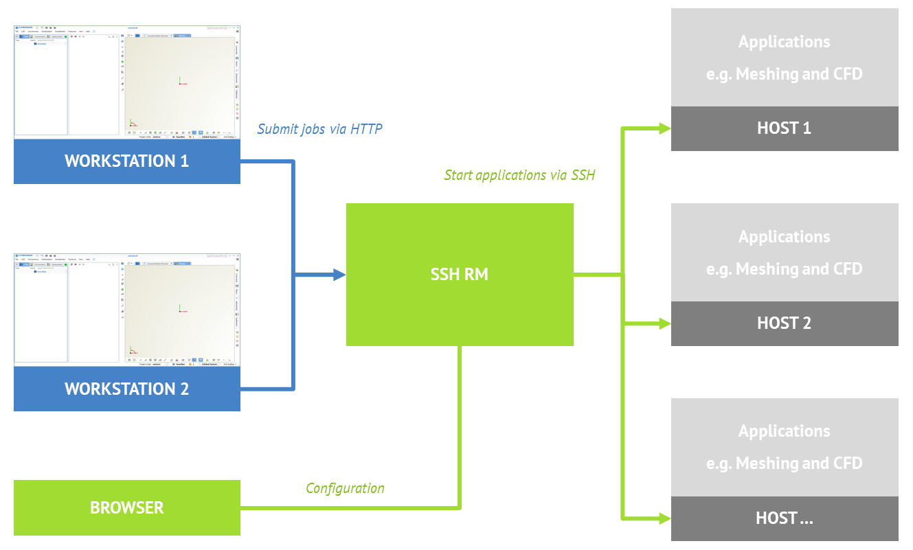
If you have the setup ready on your local machine, it is often a reasonably small effort to let it run on remote hardware resources. The simulation and geometry tools such as CAESES run in batch mode, i.e., without the need of a graphical user interface. Exactly what you need to run the entire setup on HPC clusters, for instance.
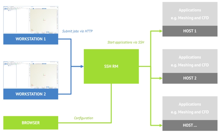
Distributing the simulation runs on remote hardware resources with tools such as SSH RM
Grid engines help you to distribute your analyses (check out more information about optimization and grid engines), and tools such as ANSYS even have their own solution for that (Remote Solve Manager RSM). To be on the safe side, make sure your CAE tools support Linux.
By the way: Weekends are really great for running optimizations! Many engineers all over this planet set up and trigger their runs on Friday so that first results can be already assessed on Monday. Sure, this works only for a subset of applications, but it’s definitely worthwhile pointing it out at least as a side note… has anybody already written an article about energy consumption in the CAE sector on weekends? ;-)
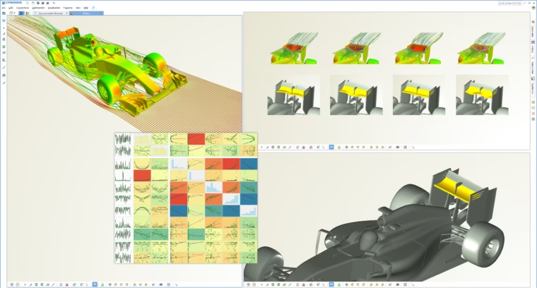
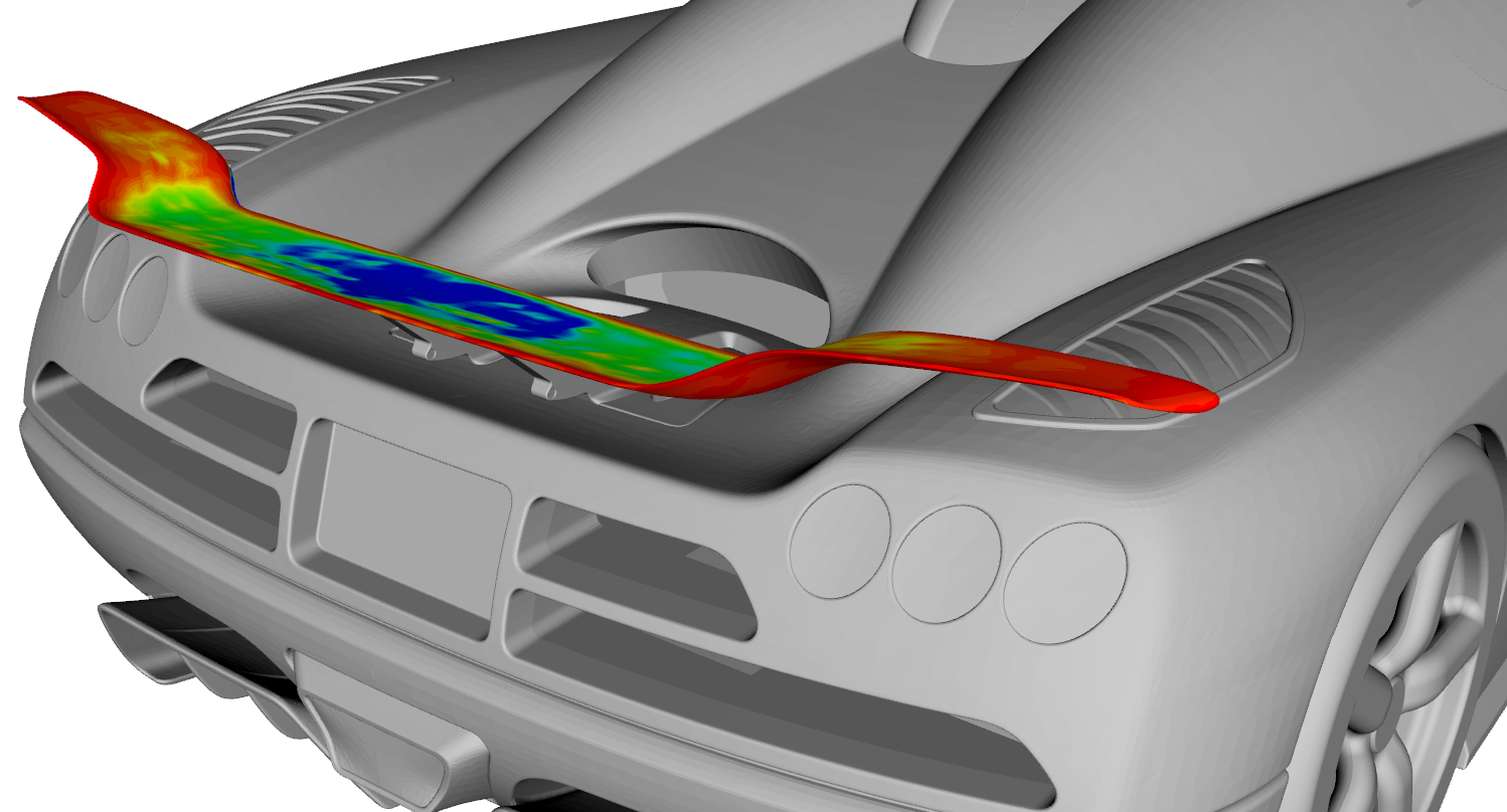
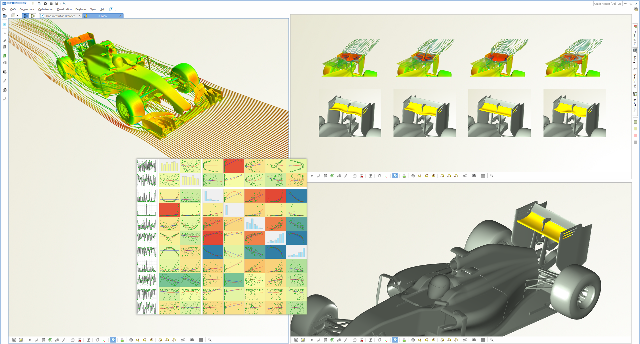
Run comprehensive aerodynamic shape optimizations and compare design candidates
More Information
CAESES is a specialized solution for robust and flexible parametric design and shape optimization with simulation tools. If you also work on aerodynamic shape optimization for aircraft components, race cars, wings, channels, ducts etc., and you are interested in trying out CAESES within your team, then please don’t hesitate to get in touch with us.