CAESES vs. conventional CAD software for component modeling
Developing a geometry that fulfills all given requirements – such as due to performance and manufacturing – is rarely a straightforward process. In many engineering projects, especially those involving aerodynamic surfaces, lightweight structures, or customized components, the challenge extends far beyond building a 3D model.
The geometry model must be robust when changing parameter values, consider manufacturing constraints, integrate with simulation workflows, and generate suitable export data for following processes and production. Even relatively small adjustments can affect multiple downstream components, making flexibility and workflow stability increasingly important throughout development.
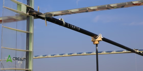
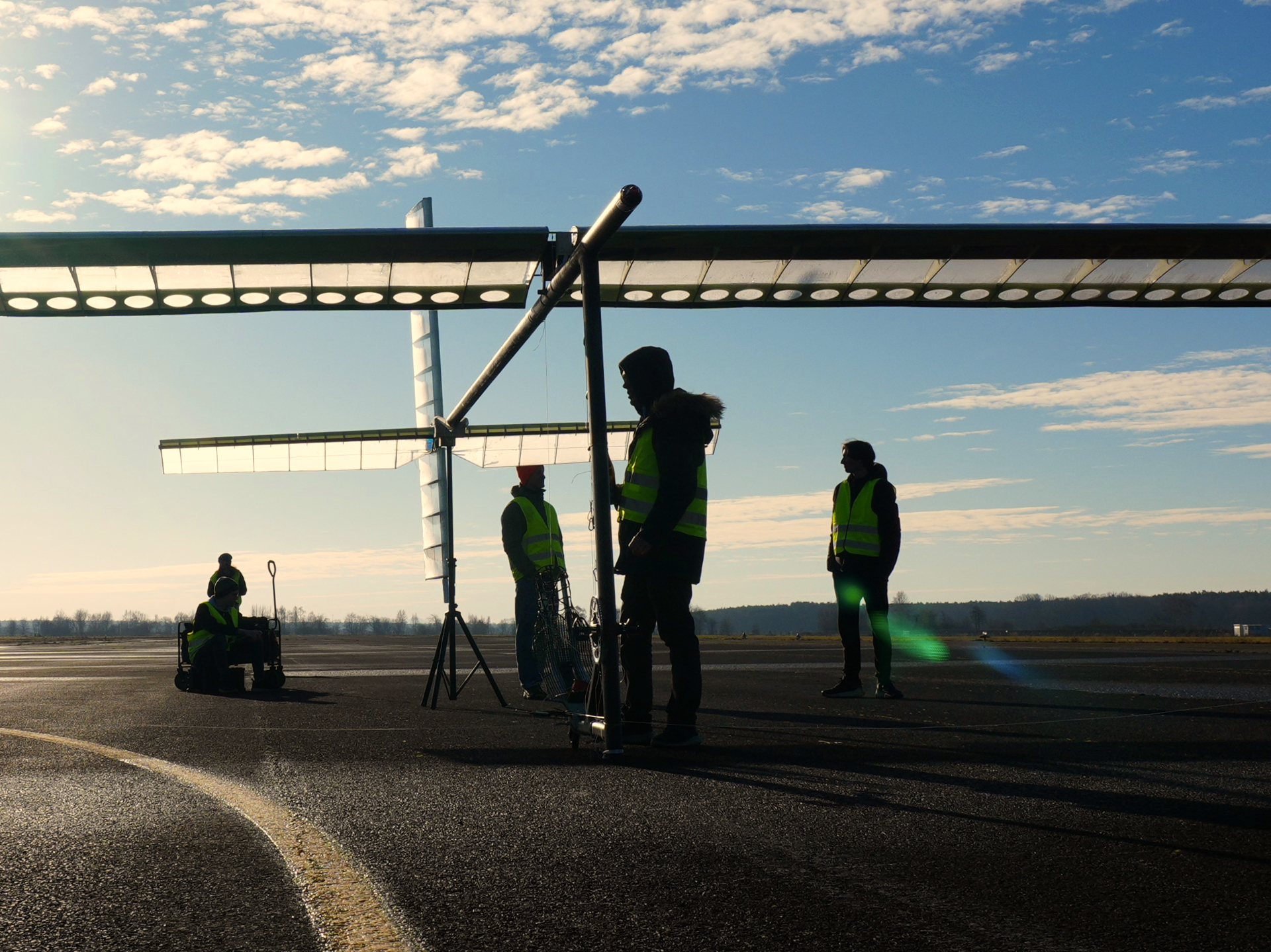
To better understand how different CAD tools approach handle these challenges, a comparison study was carried out on the vertical stabilizer of the human powered aircraft “Libelle” from Odonata e.V. as a practical engineering example.
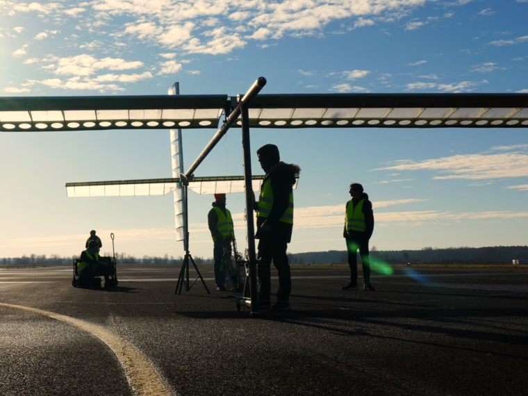
The vertical and horizontal stabilizers on the human powered aircraft (courtesy of Odonata e.V.)
The goal was to create high-performing and manufacturing-ready geometries, and more specifically, export DXF files suitable for laser cutting and hot wire cutting processes while simultaneously maintaining enough geometric flexibility to support future design changes.
The project also provided an opportunity to compare how CAESES and conventional CAD software perform in a real component design workflow.
The components
The stabilizer consists of several interconnected components manufactured using different materials and processes.
| Component | Material | Manufacturing | Note |
| Ribs | XPS | Hot wire cutter DXF file required | Incl. balsa straps, main spar positioning marking |
| Leading edge | XPS | Hot wire cutter DXF file required | |
| Mold for assembly | XPS | Hot wire cutter DXF file required | |
| Rib templates | Plywood | Laser cutter DXF file required | Required to create spar support holes |
| Spar support | Balsa wood | Laser cutter DXF file required | Must be glued at the ribs to increase compression strength |
| Main spar | Carbon fibre prepreg | Autoclave process | Required for structural simulation of laminate layup |
| Trailing edge | CF pultrusion rod | Buy from market | No CAD required |
| Balsa straps | Balsa | Cut with scalpel by hand | No CAD required |
While generating these components, several parameters needed to remain adjustable throughout development, including:
- Airfoil geometry
- Chord length at root and tip
- Thickness distribution
- Sweep
- Geometric angle of attack
This created a highly iterative workflow where geometry changes can influence multiple downstream components simultaneously.
Two different CAD approaches
Conventional CAD software and CAESES approach geometry generation differently.
Traditional CAD systems are typically built around history-based modeling workflows. Features are created sequentially, with each operation depending on previous geometry definitions. This approach works well for finalized production models, technical drawings, and assembly-focused workflows.
However, as geometry becomes more complex and iterative, and updates become more frequent, history-based workflows can become increasingly difficult to manage. Larger modifications often create broken references, unstable features, or additional manual remodeling work.
CAESES approaches the problem from a more parametric perspective. Instead of focusing primarily on sequential feature histories, CAESES builds geometry around parameters, relationships, and automated dependencies. This allows engineers to modify critical design parameters while maintaining stable downstream geometries and manufacturing outputs.
For manufacturing-oriented projects with evolving geometries, this creates a fundamentally different workflow experience.
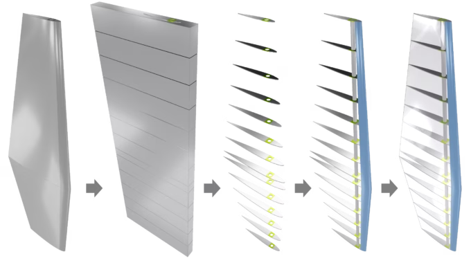
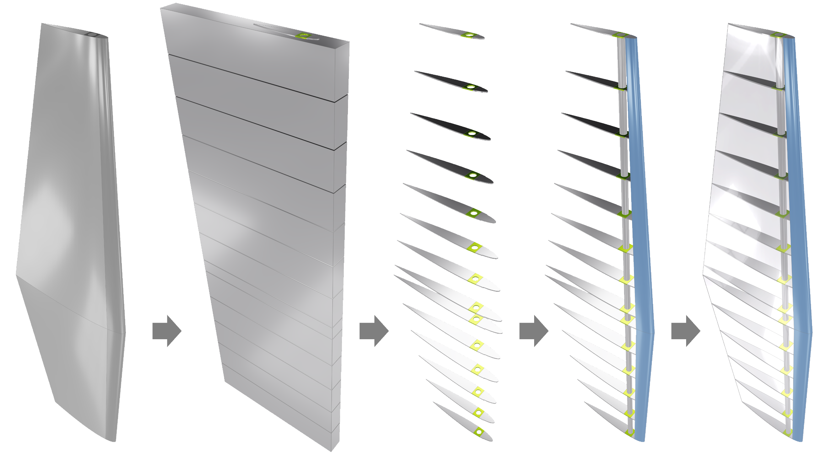
Steps in the modeling process of the vertical stabilizer
Building the geometry in CAESES
The geometry in CAESES was created using a combination of points, curves, surfaces, Breps, and Boolean operations. The overall workflow was intentionally kept compact by minimizing the number of controlling parameters while still maintaining enough flexibility for future design modifications.
Airfoil sections form the foundation of the stabilizer geometry. Parameters such as chord length, thickness, spar position, and spanwise positioning can directly be adjusted within the model definition. The spar position plays an important role because it influences the aerodynamic control behavior of the aircraft.
Using ruled surfaces between the airfoil sections, the stabilizer geometry could efficiently be generated while remaining fully parametric throughout development. One important advantage of this approach is that geometry modifications can be applied at virtually any stage without requiring large portions of the model to be rebuilt manually.
The resulting surfaces were converted into watertight Brep geometries suitable for downstream processing such as Boolean operations, simulation preparation, and manufacturing export.
As the workflow expanded, folders In CAESES were used to organize the individual manufacturing components, including ribs, molds, templates, and structural supports. This made it easier to manage increasingly complex relationships between components while maintaining a clear workflow structure.
The manufacturing geometries themselves were generated through Sub-Breps and Boolean operations. Rib sections, for example, can be created automatically based on spacing definitions and rib thickness parameters.
Instead of manually positioning each component individually, parametric relationships control the placement and generation process. This significantly reduced repetitive modeling work and simplified later geometry modifications.
Finally, the individual components were exported as DXF files suitable for laser cutting and hot wire cutting systems.
Comparing the workflows
The same geometry was also created using a conventional CAD tool by an experienced engineer familiar with both systems. The comparison focused primarily on overall engineering effort and workflow robustness rather than simply comparing feature lists. One important observation was the difference in how both systems handled geometry changes.
Within the conventional CAD workflow, the history-based modeling structure introduced additional manual work whenever larger geometry modifications affected downstream features. As dependencies became more complex, rebuilding and repairing geometry relationships required increasing amounts of time.
In CAESES, the parametric workflow structure handled these updates much more efficiently. Because relationships between components are embedded directly into the model logic, many geometry changes propagated automatically throughout the workflow. This reduced manual remodeling effort significantly and helped maintain stable manufacturing outputs even as the geometry evolved.
Development time comparison
The difference between the two approaches became particularly visible in the total development time.
Creating the complete manufacturing-ready geometry required:
- approximately 6 hours in CAESES
- approximately 14 hours in a conventional CAD tool
The difference became even more relevant once geometry modifications were introduced. While the conventional CAD workflow required additional troubleshooting and rebuilding effort, CAESES maintained a significantly more stable workflow structure during iterative updates. This was one of the clearest indicators of how parametric geometry generation can improve efficiency in manufacturing-ready engineering projects.
Where CAESES shows clear advantages
Robust geometry updates
One of the strongest advantages observed in CAESES is the ability to apply geometry changes without destabilizing the workflow.
In the given example, parameters such as:
- Airfoil definitions
- Chord lengths
- Thickness distributions
- Sweep
- Structural positioning
could be adjusted while maintaining functional downstream geometries and manufacturing outputs.
For iterative engineering projects, this level of robustness can significantly reduce manual rework.
Efficient airfoil geometry creation
Creating aerodynamic geometries using standard definitions such as NACA series or CST curves is straightforward within CAESES.
This simplifies the setup of airfoil-driven geometries and reduces manual preparation work.
Simulation-ready geometry
The generated geometry is also immediately suitable for simulation workflows, including:
- Structural analysis
- Aerodynamic analysis
- Low-fidelity simulation methods
- High-fidelity CFD workflows
This reduces the need for additional geometry preparation before analysis.
Geometry checking and visualization
CAESES also provides direct visualization of problematic geometry areas such as open edges.
This improves geometry reliability during modeling, export preparation, and simulation setup.
Strong support for free-form geometry
The flexibility of the CAESES modeling approach is particularly effective for highly customized and free-form geometries.
Custom feature definitions and parametric relationships make it easier to maintain adaptable workflows without becoming constrained by rigid feature histories.
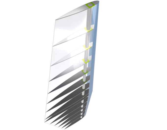
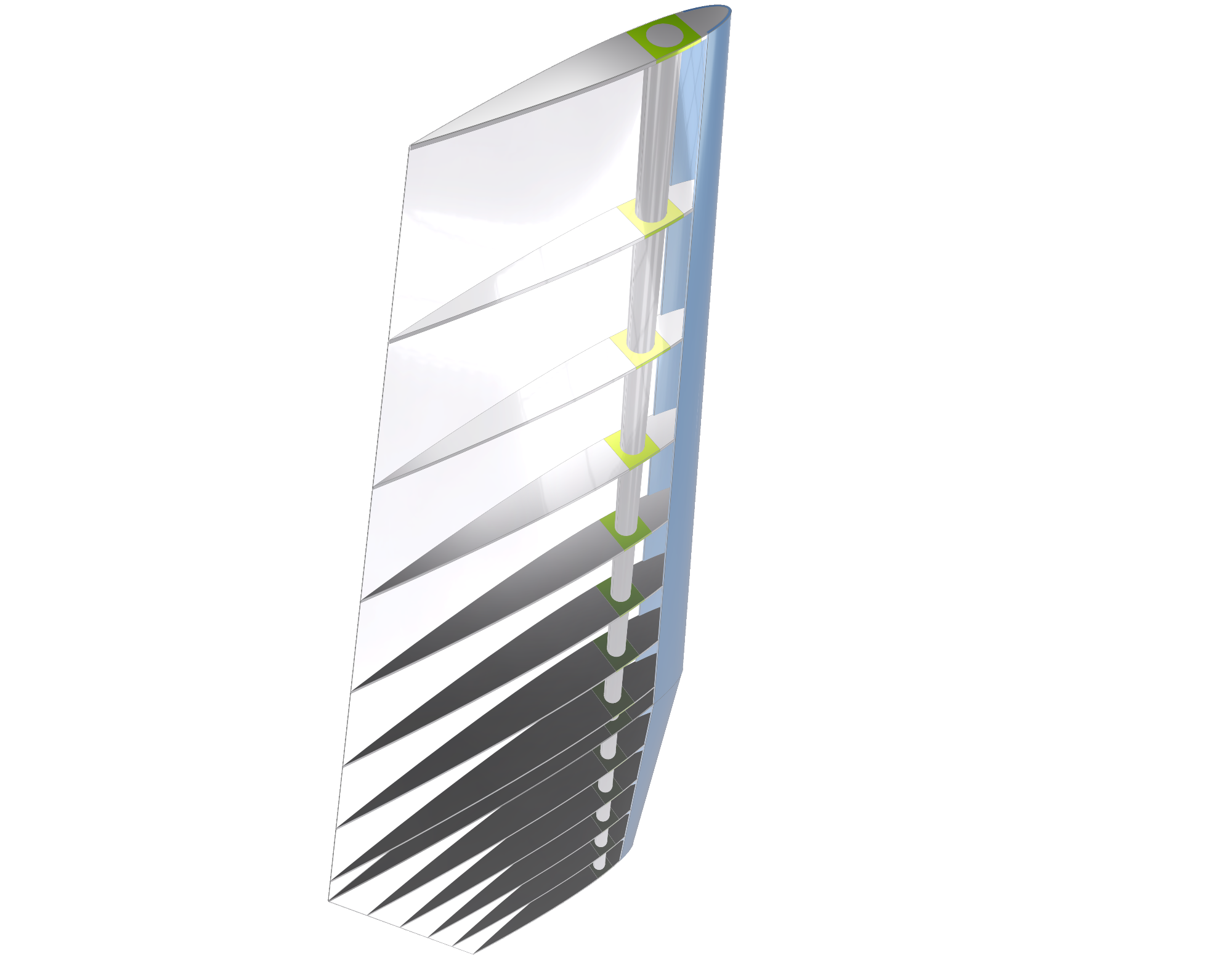
The modeled vertical stabilizer
Conventional CAD in traditional workflows
Conventional CAD systems remain widely used for production drawings, assemblies, and standard documentation workflows. Their interfaces and workflows are also highly familiar across the engineering industry.
However, this comparison highlights the limitations of history-based modeling when handling iterative geometry changes, automated manufacturing preparation, and highly parametric workflows.
As geometry complexity increases and updates become more frequent, CAESES maintains a significantly more stable and efficient workflow structure throughout the project.
Final thoughts
The comparison demonstrated that both CAESES and conventional CAD software are capable of generating manufacturing-ready geometry.
However, the workflows differ significantly once geometry flexibility, iterative updates, simulation integration, and automated manufacturing preparation become important requirements.
Conventional CAD systems remain highly effective for production-focused engineering tasks and standardized documentation workflows.
CAESES demonstrated clear advantages in:
- Parametric geometry generation
- Robust handling of design changes
- Automated manufacturing preparation
- Simulation-ready geometry workflows
- Free-form geometry modeling
For engineering teams working on aerodynamic surfaces, lightweight structures, or highly iterative component manufacturing projects, these advantages can translate directly into reduced manual effort, faster geometry updates, and more efficient development workflows.
As engineering processes continue to become more simulation-driven and data-centric, robust parametric geometry workflows are becoming increasingly important across advanced design applications.