Design and Optimization of Valves
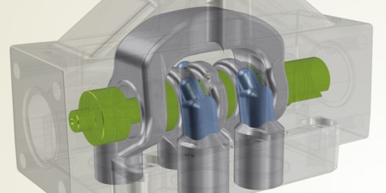
The design and optimization of valves is one of many applications where using CAESES® to robustly automate the processes of systematic geometry variation and analysis of the generated variants with a suitable CFD solver can lead to significant reductions in time-to-market, as well as to a truly optimal design within the specified constraints.
Valves are devices that control, direct or regulate the flow of a fluid by opening, closing or partially obstructing various passageways. In an open valve, fluid flows in a direction from higher to lower pressure. The primary objective in the optimization of a valve is usually the improvement of the flow rate through the valve at a defined pressure drop, often expressed as the so-called flow coefficient or flow factor, a relative measure of its efficiency at allowing fluid flow.
Example Case: Valve Optimization with SimericsMP+
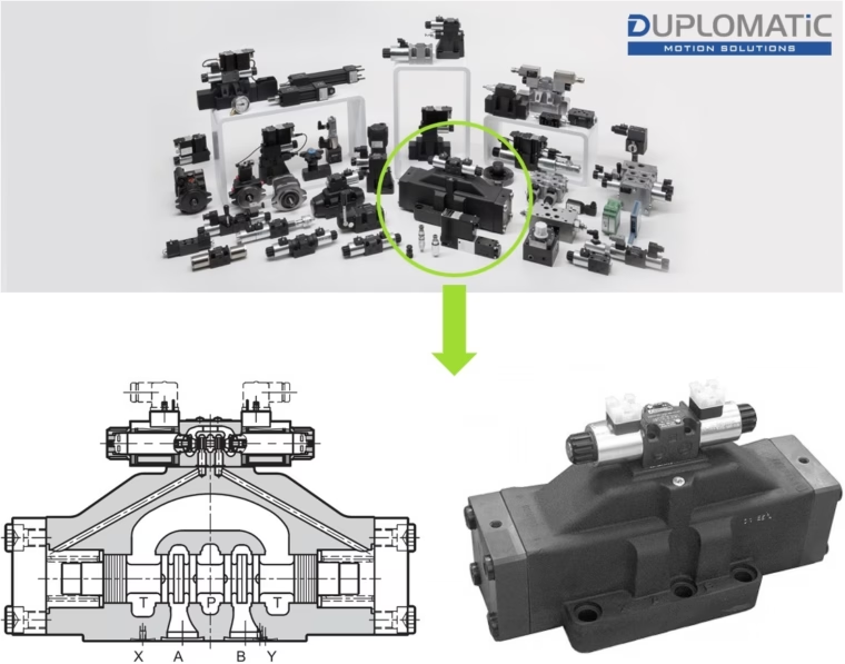
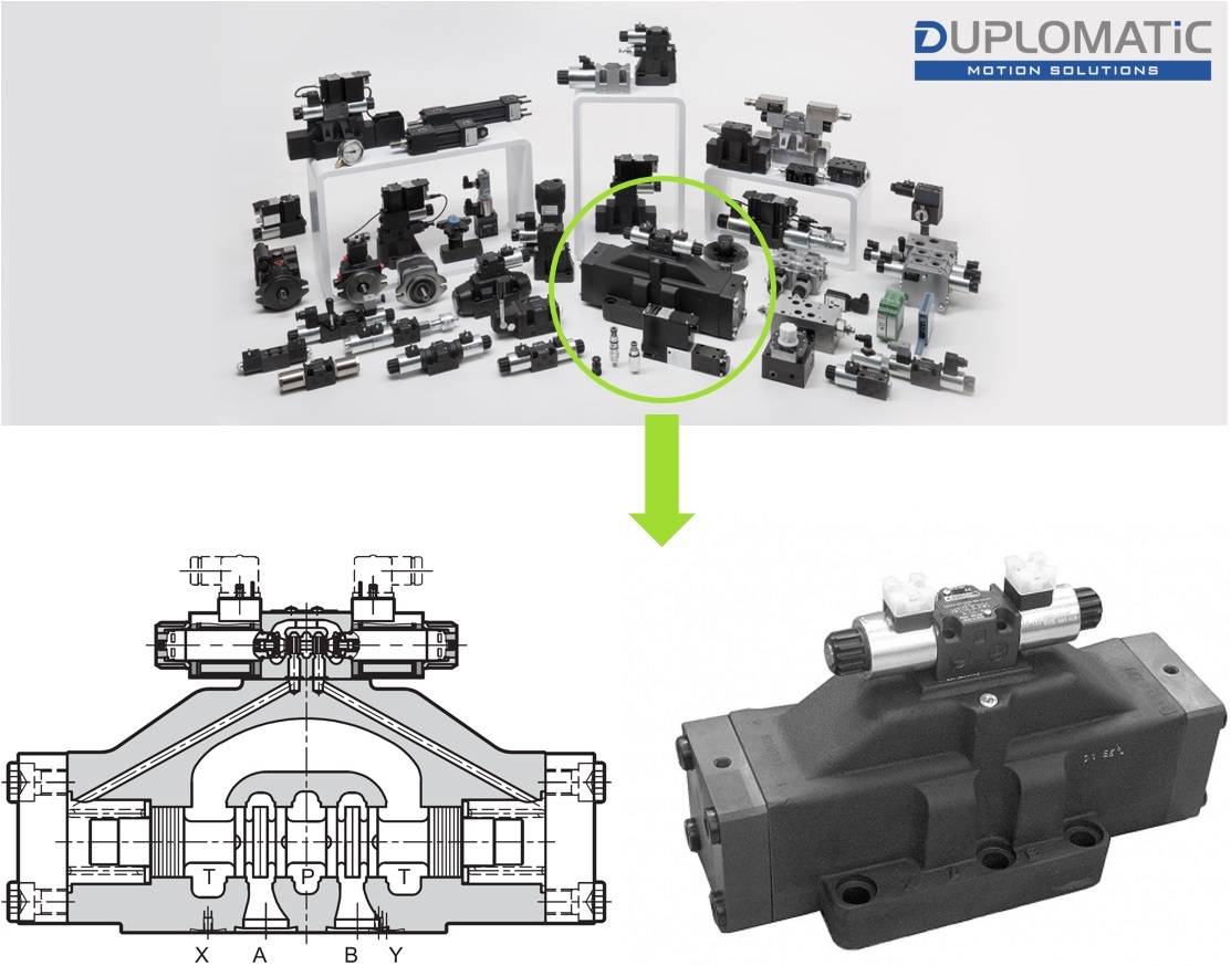
Duplomatic valve selected for the optimization study
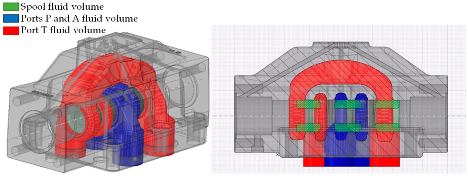
The following sections describe an optimization study that was carried out to demonstrate the workflow for valve optimization using CAESES® in combination with SimericsMP+ as CFD solver. The object of this study was a four-way spool valve from Duplomatic Motion Solutions, which is a pilot operated distributor with solenoid or hydraulic control. In particular, the shape of two ports of the valve was optimized in order to obtain the highest possible mass flux at an imposed pressure drop of 5 bar. For optimization purposes, the valve was simulated with a fixed spool position so that only ports P and A (in blue in the following figure) were connected through the spool port recesses (green in the following figure), a typical operating condition.
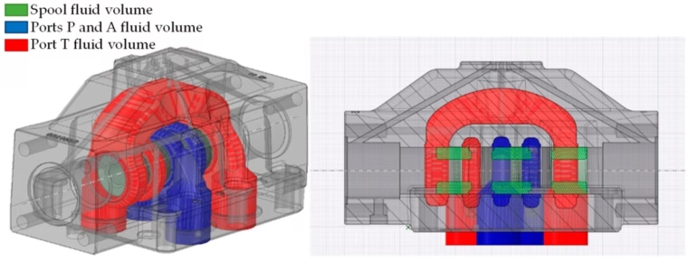
Valve components involved in the optimization
Geometry Variation Setup
The affected ports were removed from the original CAD model and replaced with geometry parts parameterized in CAESES®. For each of the two considered ports, the same set of 9 parameters was selected as free variables for the optimization. These parameters control the shape of the different form features for the internal passageways of the ports. The following animations illustrate the effect of the individual parameters on the geometry model.
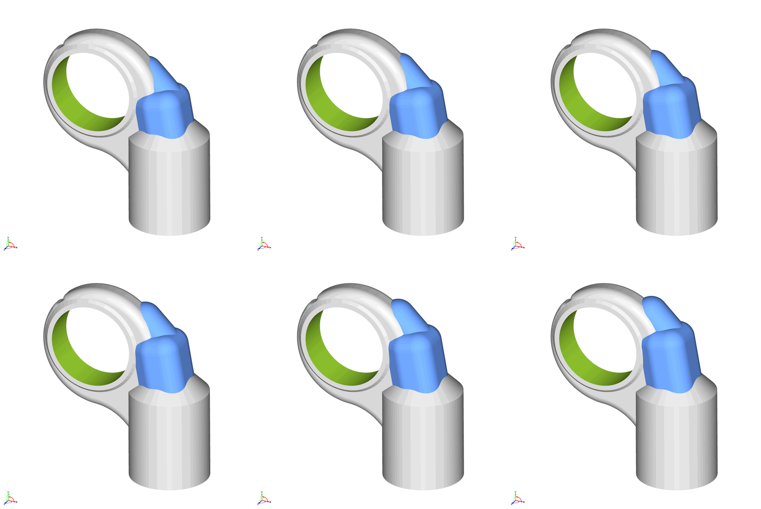
Box Height
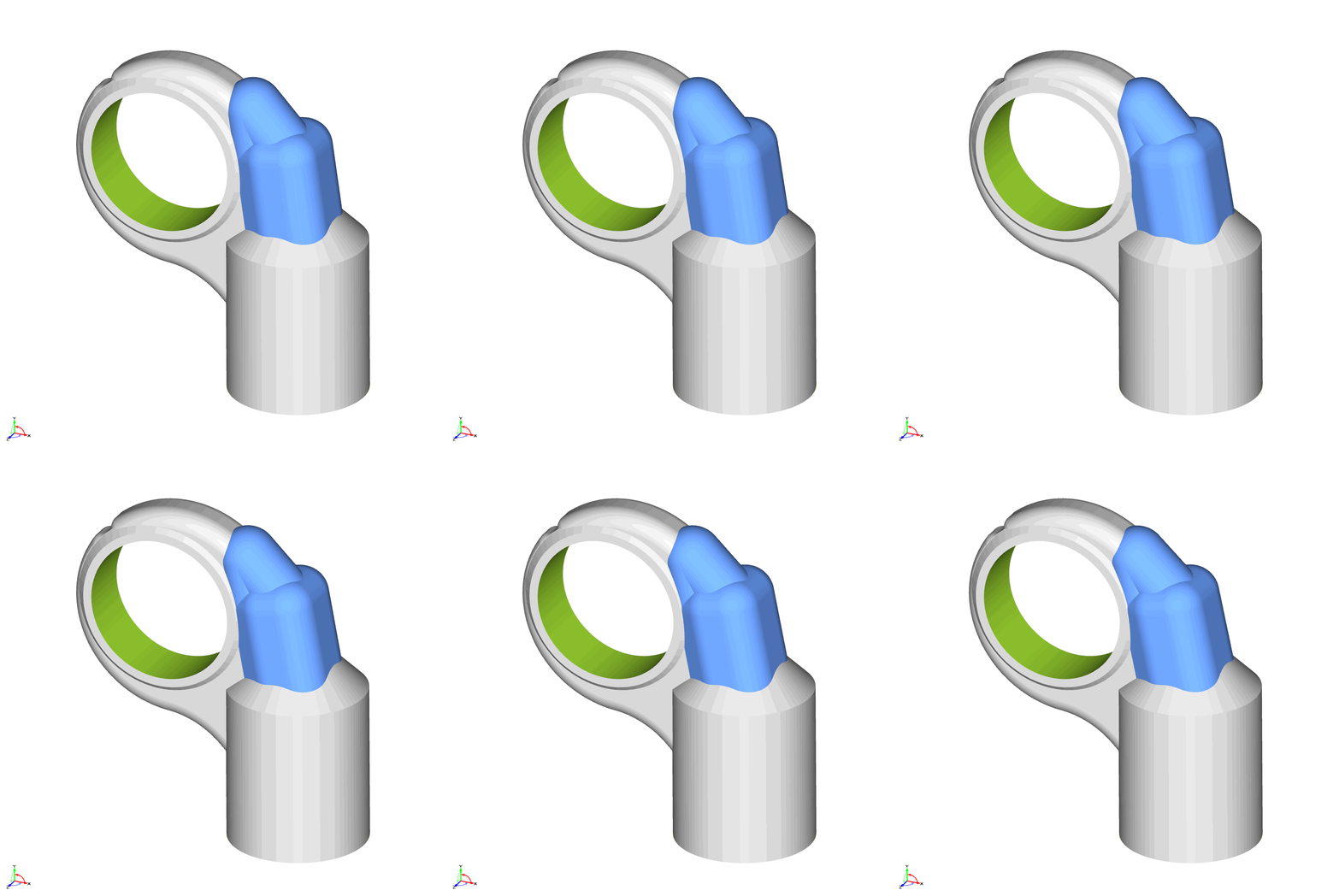
Box Rotation
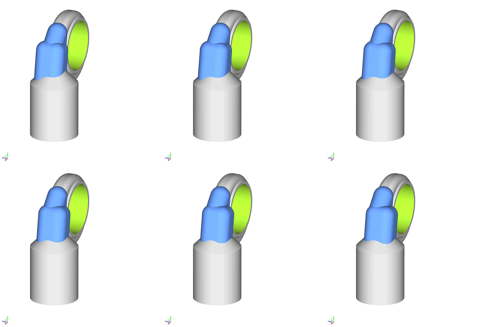
Box Shift
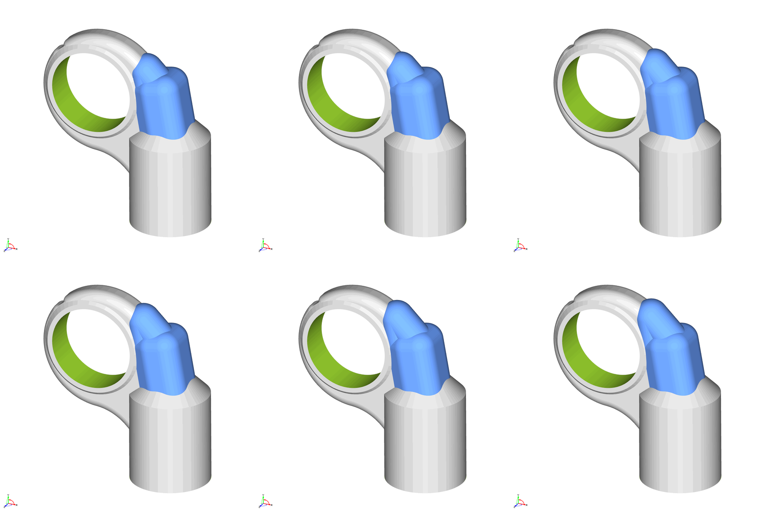
Cap Height
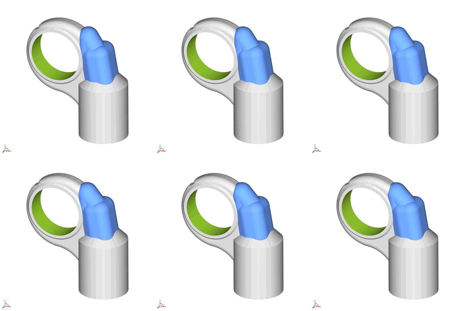
Cap Rotation
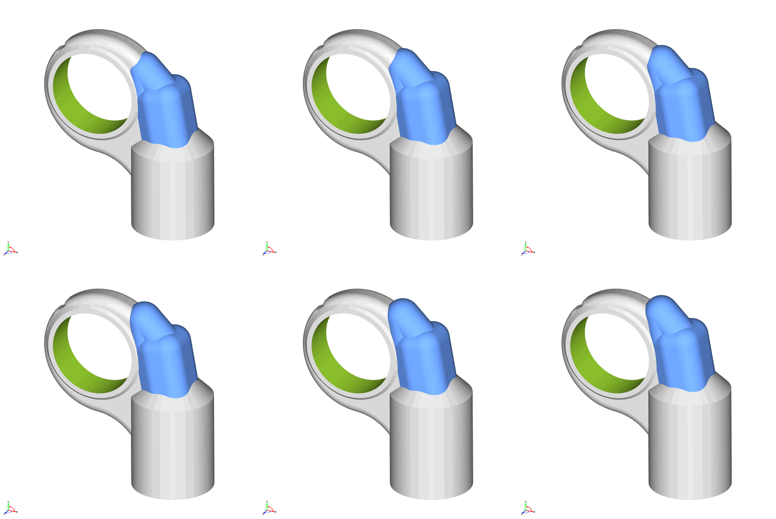
Cylinder Height
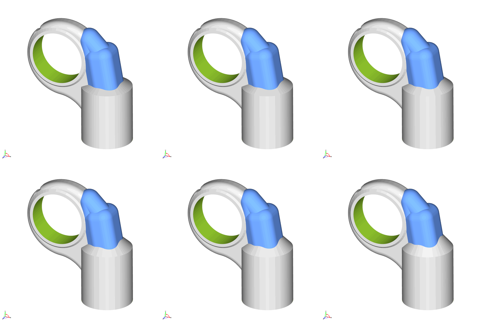
Cone Angle
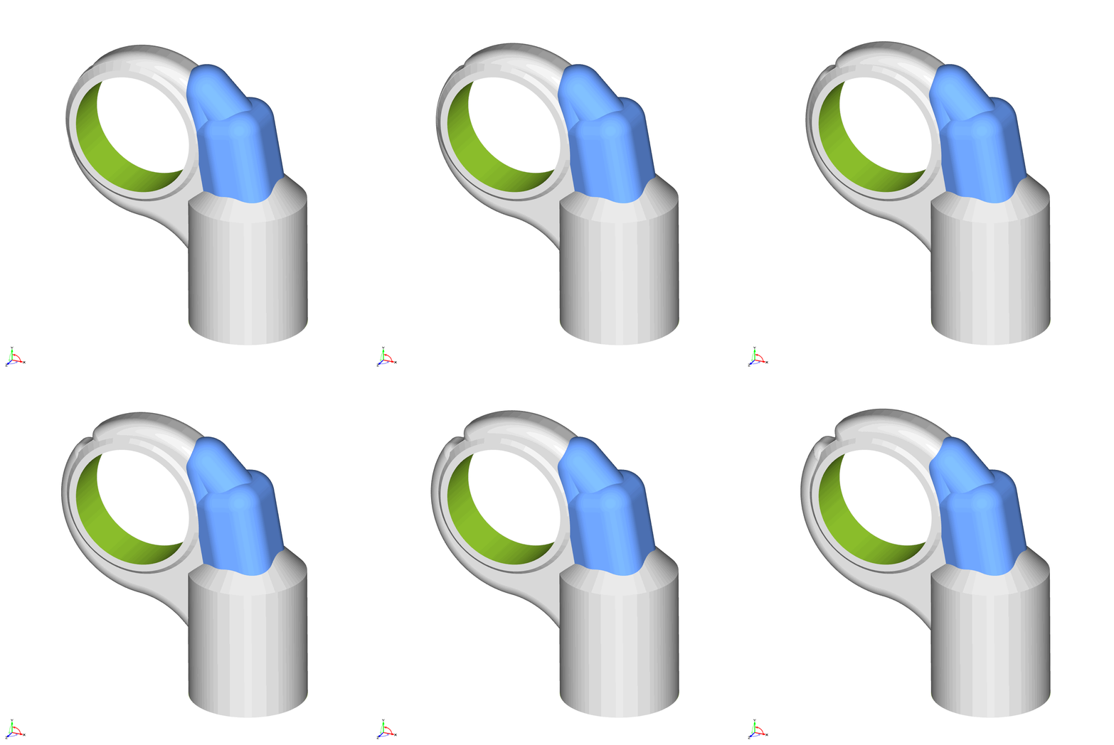
Outer Radius
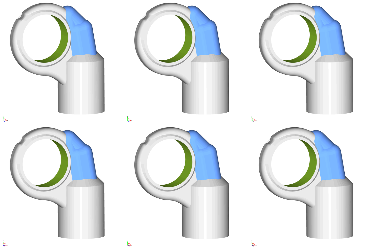
Bottom Fillet
SimericsMP+ Automation
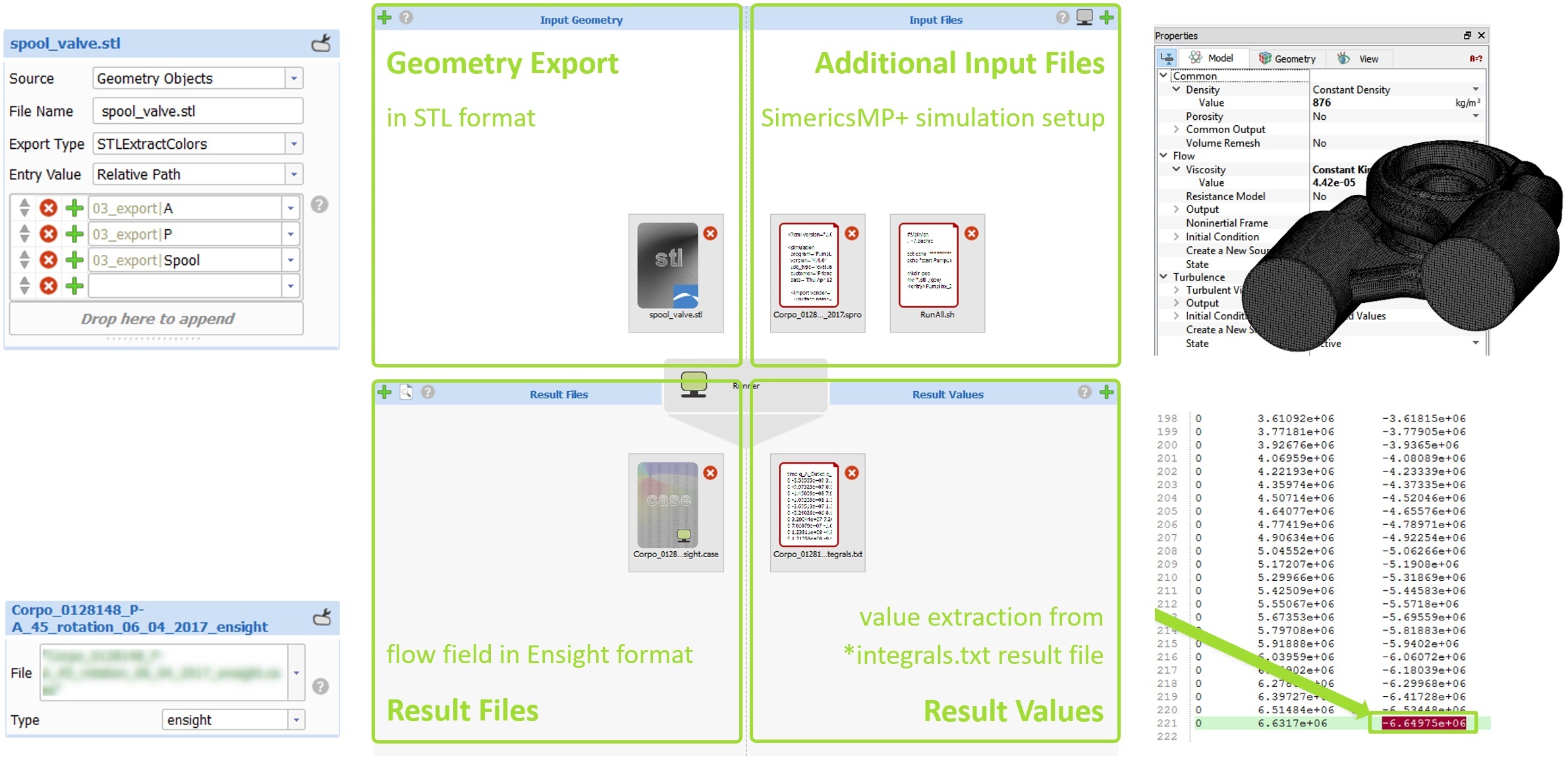
SimericsMP+ was integrated using the CAESES® Software Connector for the analysis of the generated geometry variants. The geometry is exported in STL Extract Colors format, where each color defined for a part of the geometry in CAESES® is exported into a separate STL file. This allows SimericsMP+ to easily identify boundary patches and keep the associativity to related settings (e.g. mesh settings or boundary conditions), allowing automated mesh regeneration. The simulation setup is carried out in the SimericsMP+ user interface once and saved in the *.spro file, which will subsequently be exported by CAESES® for each variant.
On the result side, an Ensight Gold file with the complete flow field is imported, as well as a text file with the time history of integrated values. The latter is used to extract the objective for the optimization, the flow rate.
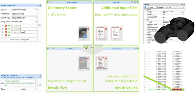
CAESES® Software Connector setup for the integration of SimericsMP+ in the valve optimization process
Optimization Process and Results
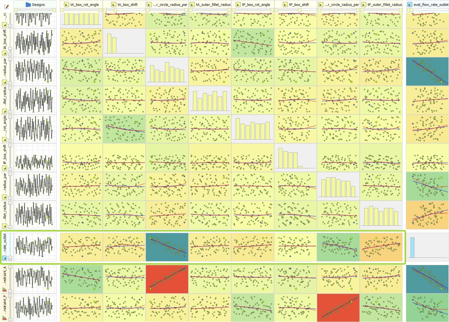
The overall optimization process was structured in three phases. In the first step, a preliminary DoE that included all 9 parameters for one of the two ports (A) was carried out with 100 design variants. Based on those results, the 4 most influential parameters, i.e., the parameters with the strongest correlation to the objective function (box rotation, box shift, outer radius and bottom fillet radius), were identified and selected for a second DoE. Here, the selected parameters were applied to both ports (A and P) and 90 designs were analyzed. Finally, in the last step, a local optimization was carried out starting from the best design of the preceding DoE and the same set of parameters and an additional 50 designs.
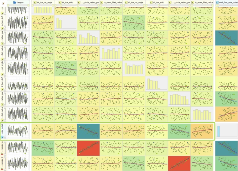
Correlation chart for the valve port parameters
Compared to the baseline design, the optimized design at the end of this process showed an improvement of about 9% in mass flow rate, whereby the DoE phase contributed 7% and the final local optimization an additional 2%. While not being a strict constraint, the volumes of the ports were monitored during the optimization process, but all considered variants were well within the tolerated bounds. Experimental tests, carried out at the Industrial Engineering Department of the University of Naples, confirmed the results of the optimization. It is also worth noting that the design had previously been optimized with a manual iterative procedure by the Industrial Engineering Department reaching similar results, albeit within a time frame of several months vs. a few days for the automated procedure executed with CAESES®.
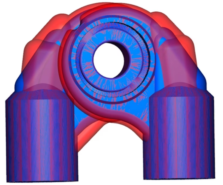
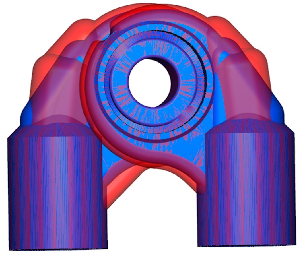
Comparison of baseline (blue) and optimized (red) valve port geometries
We were very impressed by the speed and efficiency of the CAESES/SimericsMP+ procedure. Using a traditional approach based on incremental geometry modifications and CFD validation, it took us roughly 10 times longer to achieve the same result.
Michele Pavanetto
Technical Director, Duplomatic Motion Solutions