Aerodynamic Bicycle Wheel Design Optimization
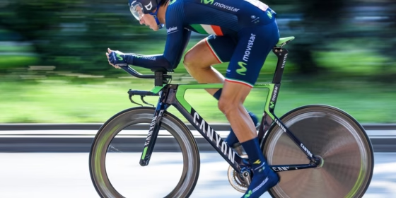
The aerodynamic optimization of bicycle wheels can lead to decisive gains in running pace. Nowadays, aerodynamic performance is one of the key factors considered when racing cyclists purchase new equipment, as the aerodynamic drag is known to be the main source of losses in cycling, causing between 70% to 90% of total losses in flat road races. Lateral forces felt due to a high wind yaw angles also have an impact on equipment selection, with users opting for shallow wheel choices in these conditions due to the buffeting effect deeper rims can have.
Work carried out by Greenwell et.al. concluded that the drag contribution from the wheels alone is on the order of 10% to 15% of the total drag and that by improving wheel design, an overall reduction in drag of more than 3% is possible. This would suggest that the outcome of races can be dramatically affected by equipment choice. Especially considering the extremely small margins that decide the outcomes of races. The difference in finishing time for many races can be as low as a few seconds from a race spanning multiple hours.
To date, there has been a great amount of work done to test cyclists, bikes and wheels both in the wind tunnel and through CFD, although, it is difficult to make a direct comparison between designs due to different setups for both wind tunnel and CFD tests.
Far less work has been carried out regarding the optimization of rim shapes for different conditions and yaw angles. The aim of this project was to investigate the aerodynamics involved in bicycle wheel design, and to optimize and design a very low drag bicycle wheel rim shape using CAESES & TCFD.
Bicycle Rim Section Optimization
The aims set for the bicycle wheel rim shape optimization were to first determine the fastest shape at an angle of attack (AOA) of 0 degrees and then review how this shape performs at higher AOA. This is due to fact that for high level cyclists, who are likely to be using performance wheels, lower AOA were determined to be the most common. A section of the wheel was analyzed both facing forward and backwards, as the airflow meets the front portion of the wheel and flows over the forward-facing section, then travels to the rear of the wheel, where it travels over the backwards-facing section. It was important to investigate the behavior over both portions and optimize both. This could effectively be done using CFD and wind tunnel testing as the sections tested could fit into the manufactured wind tunnel. More emphasis was placed over the front rim section, especially at low AOA, as the rear section will have turbulent incoming air from the front section, hub and spokes.
Optimization Workflow
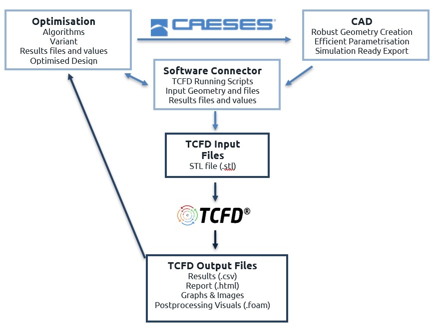
CAESES provided the CAD environment including robust and easy geometry variation, efficient parametrization and simulation-ready export. The parameterized model was exported as surface geometry, for which a CFD simulation setup was created in TCFD. This setup was based on previously determined settings for a NACA airfoil section that where validated with wind tunnel experiments (the same wind tunnel used later to test the wheel rim design). The script and input files that control the mesh generation and CFD simulation process were integrated into the CAESES Software Connector . Finally, an optimization process could be started in CAESES, whereby each generated geometry variant was automatically meshed and simulated with TCFD.
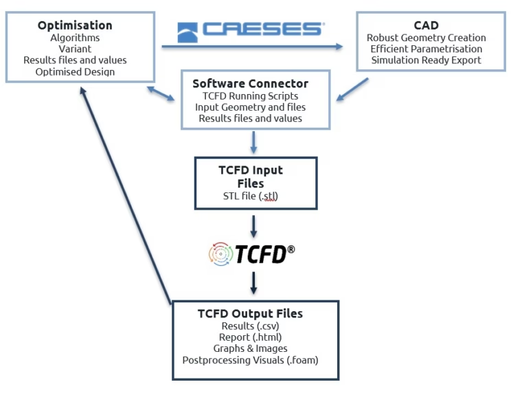
Workflow for aerodynamic bicycle wheel optimization
Rim Shape Parametrization
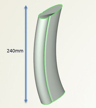
The modeling process included a few steps. Firstly, the cross section shape was defined, including all necessary shape parameters. This cross section was then revolved by 360 degrees to give the full wheel geometry. For this optimization, a 240mm high section was cut out to simplify the problem.
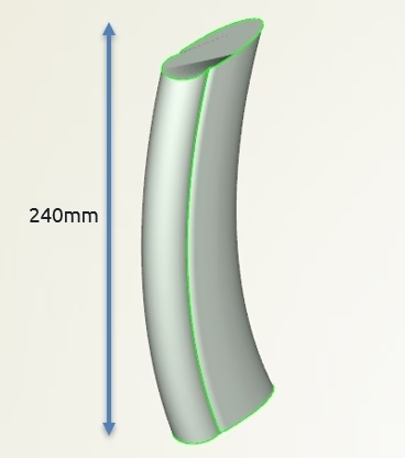
Rim section used for optimization
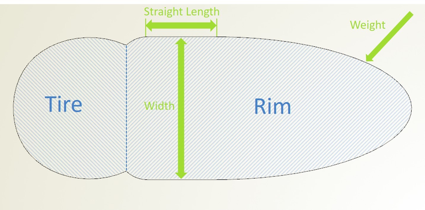
A few of the available parameters were selected for the optimization of the rim shape and their ranges defined. These parameters were:
- Weight – This parameter is used to describe the shape of the curve. A higher value defines a more blunt curve, while lower values yield a sharper profile.
- Width – This determines the width of the rim (the tire is fixed at 25 mm).
- Straight Length – This length is the portion of the rim which is straight before the curve begins.
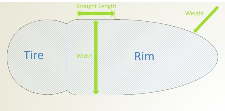
Cross section
Optimization Process and Results
The optimization was performed on an Intel Xeon E5-2680 v2 CPU with 20 cores. One design loop, including mesh generation and the TCFD simulation, took about 60 minutes. All simulations were run sequentially on the described hardware. For the 3 selected design variables, an initial set of 40 design variants was evaluated, which took about 2 days to simulate. This exploration of the complete design space was performed by a DoE using a Sobol sequence. The results from this step already gave a very good indication regarding correlations and trends. Then, a further 20 designs were automatically evaluated using a local optimization starting from the lowest drag design from the initial set of designs.
In this optimization, the rim drag obtained from the TCFD simulation was determined to be the objective function. Both the front and rear portions of the rim were optimized independently and then combined to find a suitable compromise.
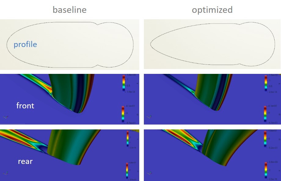
Before the actual optimization process, the baseline design was simulated for both the front and rear portions.

Baseline front

Baseline rear
After 40 simulations we get the best designs listed in the table below.

Best designs front

Best designs rear
The reason for the difficulty in reducing the drag on the rear part of the wheel is that the tire is on the aft of the model. Further work into surface features on the tire, such as dimples, may reduce the drag further.
From the results, a variant with the best balance between the optimizations from the front and the rear was chosen. The optimization process reduced the drag value by 13% on the front portion of the rim and 2% on the rear portion of the rim when compared to the baseline design. The final outcome of this study is summarized in the table below:

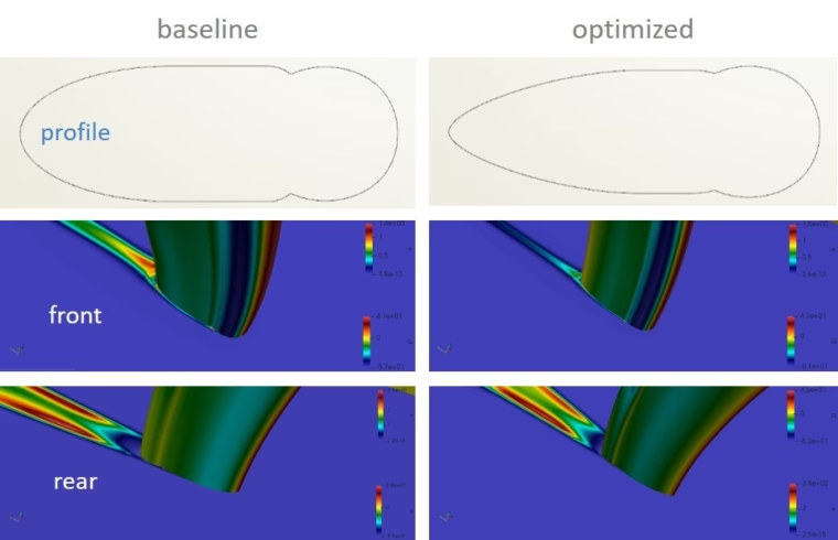
Comparison of baseline and optimized design
Wind Tunnel Testing
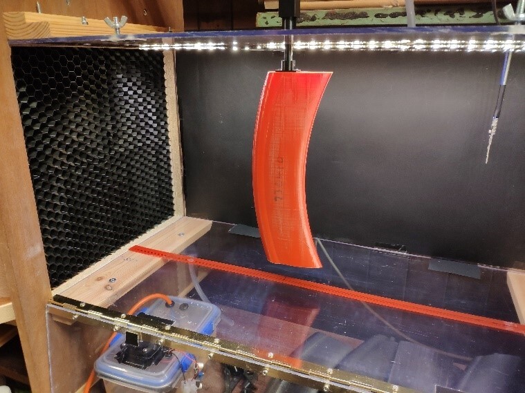
Several selected design variants were tested in the wind tunnel to verify the CFD results The model was capable of being attached both facing forwards and backwards to allow the front and rear sections to be tested, as well as being rotated in prescribed increments to test different angles of attack. All models were tested from ‑16 degrees to 22 degrees. This allowed investigation into not only the models at low yaw AOA but also stall angles. The drag values calculated from the CFD solver matched the wind tunnel values closely, which gives additional confidence for using this optimization process to develop fast bicycle rim shapes.
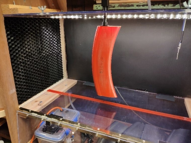
Wind tunnel testing of the bicycle rim section
About the Author
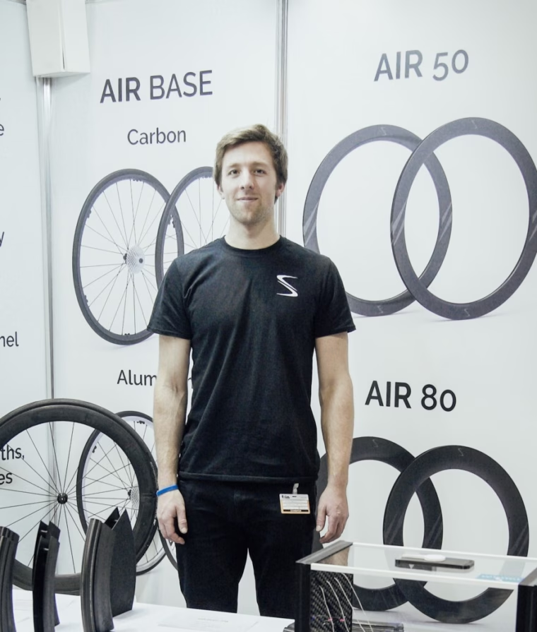
Thanks a lot to Daniel Cain from Streamline Cycling, for providing these interesting details and images for this blog post.
Daniel Cain is the founder and CFD specialist at Streamline Cycling, a company that develops aerodynamic bicycle wheels and equipment. He graduated with a MEng in Aero-Mechanical Engineering from Strathclyde University in Glasgow, before specializing in product design and CFD. He is currently working towards the launch of his product range of bicycle wheels.





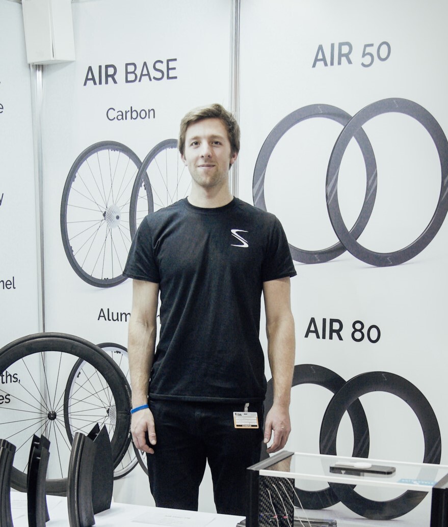
“CAESES has been an integral part of the product design process, allowing us to easily optimize many parameters that affect the aerodynamic performance of bike wheels. CAESES is extremely important in allowing us to explore the design space intelligently and refine designs. Many hundreds of designs can be automatically evaluated, and complete Pareto fronts generated.”
– Daniel Cain, founder and CFD specialist at Streamline Cycling
More Information
You can find more information about the bicycle wheel optimization case by downloading the full report. Further general information about the Streamline Cycling can be found on their website.
Feel free to contact us if you have any questions about this or other applications.