Turbine Blade Cooling
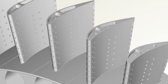
In the context of gas and steam turbines, the design and optimization of turbine blade cooling structures is a critical task for turbomachinery engineers. The higher temperatures the first turbine stages can endure, the higher thermal efficiency can be realized. There are literally unlimited possibilities in terms of how the inner structures are designed and fine-tuned, to prevent turbine damage at high temperatures under high centrifugal stresses. Finally, the most efficient way of solving this design problem comes down to an automated shape optimization process, where the design parameters of such a cooling structure are varied automatically. For each generated design, a simulation run is conducted and some objective functions related to the stress, temperature, pressure, etc., are evaluated and a ranking is assigned to each design candidate. Optimization strategies, such as genetic algorithms and response surface methods help to minimize objective functions in an automated and efficient way, to find the optimal design in the shortest time.
Geometry for Turbine Blade Cooling Structures
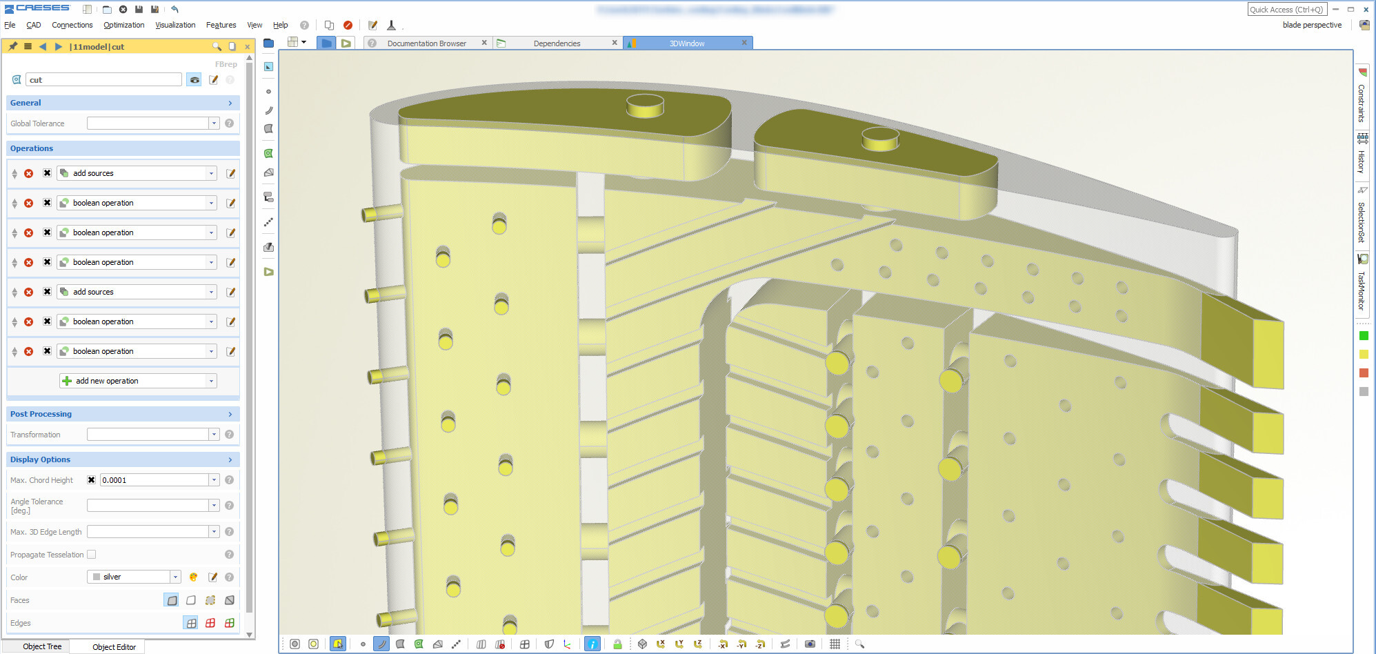
In order to be able to run shape optimization studies for turbine blade cooling structures, you have to create a flexible parametric model that can reliably generate a large variety of design candidates. Ideally, without breaking the solid geometry during the variation process. CAESES provides a comprehensive toolkit for the creation of inner air channels and variable hole configurations. In particular, Boolean operations are used for generating the solid turbine blade by merging the inner parametric channel model with the outer blade surface geometry.
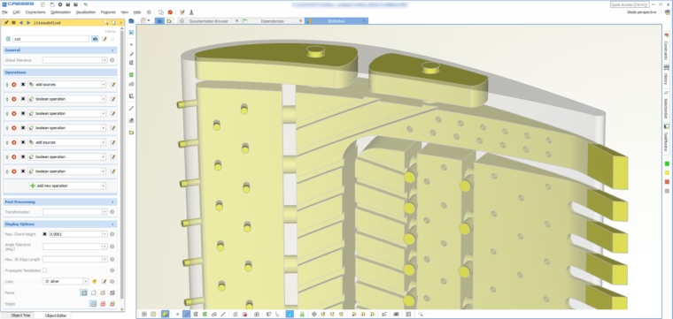
Parametric turbine blade cooling structures in CAESES
Channel Design Parameters
The following animations show a few parameter changes for an example model in CAESES. The number of the inner ribs is an essential design parameter and can be controlled:
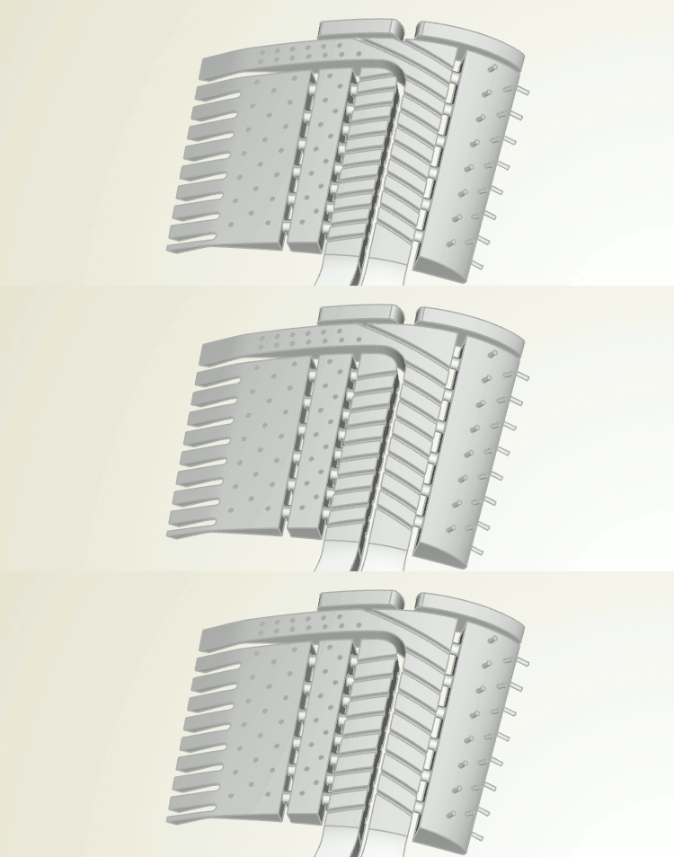
Automatically change the number of the inner ribs to find the optimal design
Not only the number of these channels is important, but also the different angles that you can apply to these structures, for which another parameter can be introduced:
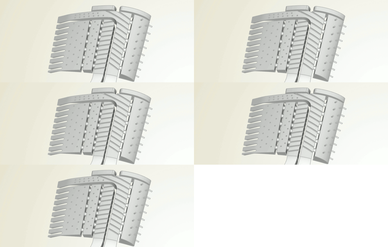
Vary quantities such as the angle of the inner channels for the turbine blade cooling
For turbine cooling structures, the number of holes and their location within the blade are standard controls that turbine engineers need:
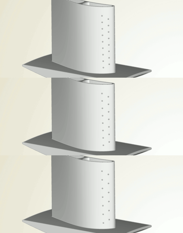
Vary the number of holes for the turbine blade cooling
The variation of the holes’ diameters is shown in this last animation and can be also controlled by a single parameter:
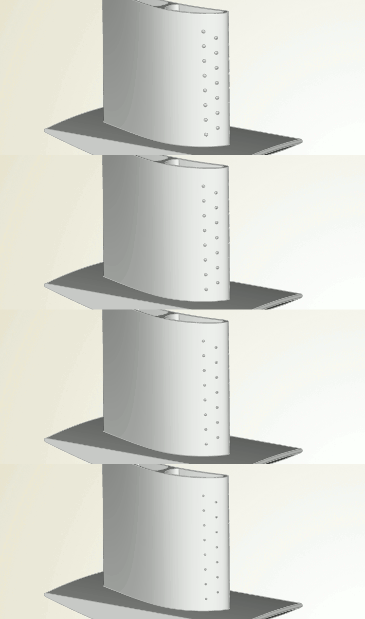
Change the diameter of the holes
These are only a few parameters, but there can be a variety of shape controls, which are all simultaneously changed within optimization loops. Of course, there are also some geometric constraints that need to be considered as well. This makes sure that you create only feasible design candidates during your studies. Note that we do not cover the fillet geometry (between the blade and the hub) in this blog post, to keep things short. There is another article about a turbocharger turbine, which also involves blade-hub fillets for consideration of stress and fatigue issues.
Squealer Tips and Film Cooling Holes
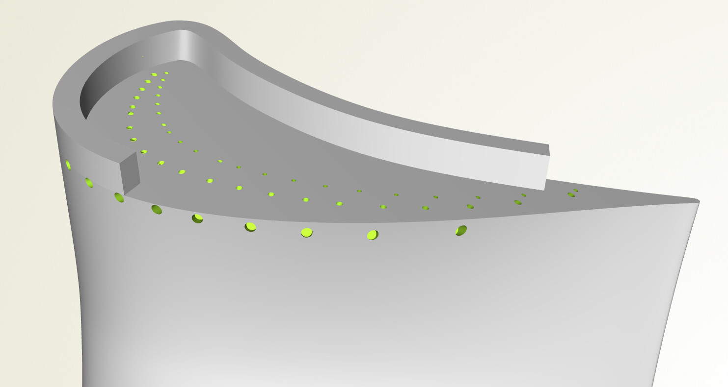
Apart from the internal cooling passages detailed above, there are other structures that determine the cooling efficiency of a turbine blade. The tips of turbine blades experience especially large thermal loads due to hot gases flowing through the gap between blade tip and shroud at high velocity. Apart from the thermal effects, this flow across the tip increases the losses in the flow. A recessed tip — a so-called squealer tip — can be used to reduce these effects. The tip gap can become smaller without risk of mechanical failure, which reduces the flow rate through the clearance. Also, the recess in the tip is believed to increase the resistance to the flow and can include cooling holes.
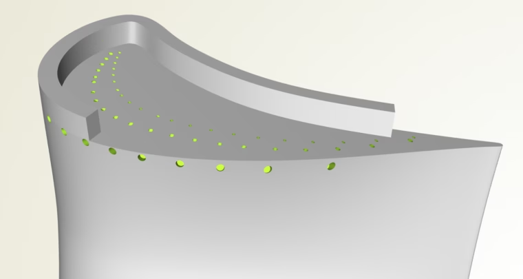
Turbine squealer tip modeling in CAESES
Turbine squealer tip modeling in CAESES[/caption] Cooling holes are generally dispersed throughout the blade and connect the internal cooling passages with the outer surface of the blade. The steady stream of exiting air creates a film on the blade surface that additionally protects it from exposure to the hot gas. The cooling effectiveness and persistence of the cooling film can be improved by reducing the velocity at the exit of the holes, i.e., by creating holes with a diffuser shape exit portion. Different shapes of this diffuser portion further influence the flow and can be explored for an optimal result. You can find some examples for squealer tip and film cooling hole optimization in this presentation given by Siemens at our last users’ meeting.
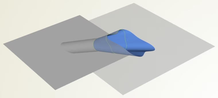
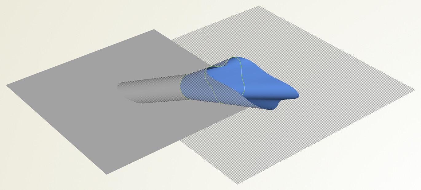
Turbine film cooling hole with diffuser
More Information
The turbine blade cooling structures of this blog post originally came from our partner NJTF, and the full article with a few more screenshots and animations can be found here (Chinese). CAESES provides turbomachinery capabilities for geometry modeling, process automation and shape optimization strategies. Feel free to contact us if you have any questions about this post, or if you are interested in creating and using parametric cooling structures for turbine blades.