Ship Hull Optimization: Generalized Lackenby
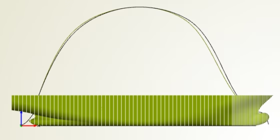
Most of our maritime CAESES® users probably know about this shift transformation for optimization of ship hulls: the Generalized Lackenby. It has been part of CAESES® for many years now, and it helps naval architects to modify an existing (e.g. imported) hull with just a few clicks. Ok, changing a ship hull is not such a big deal, actually you can do this with any CAD system. The interesting part of this Lackenby transformation is that you can shift volume of the hull forwards or backwards (i.e. in longitudinal direction) while automatically fulfilling user-defined constraints. Typical constraints are the longitudinal position of the center of buoyancy as well as the change of the displacement. And, the shift is very smooth!
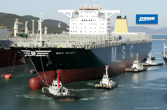
As a result, you can quickly optimize a hull shape and maintain the most important characteristics and quantities, e.g. to ensure stability criteria and displacement matters in the next design stage. Check out this optimization project of a mega boxer, where the Generalized Lackenby was used for a systematic study and a formal shape optimization.
So how does it actually work?
Initial Hull
For an imported hull geometry, you can directly calculate the relevant hydrostatic values in CAESES®, in particular, the sectional area curve. This curve is the main input for the Generalized Lackenby. It provides information about the center of buoyancy and the displacement.
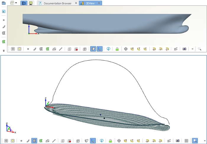
Hydrostatic calculation of the initial hull
Lackenby Shift
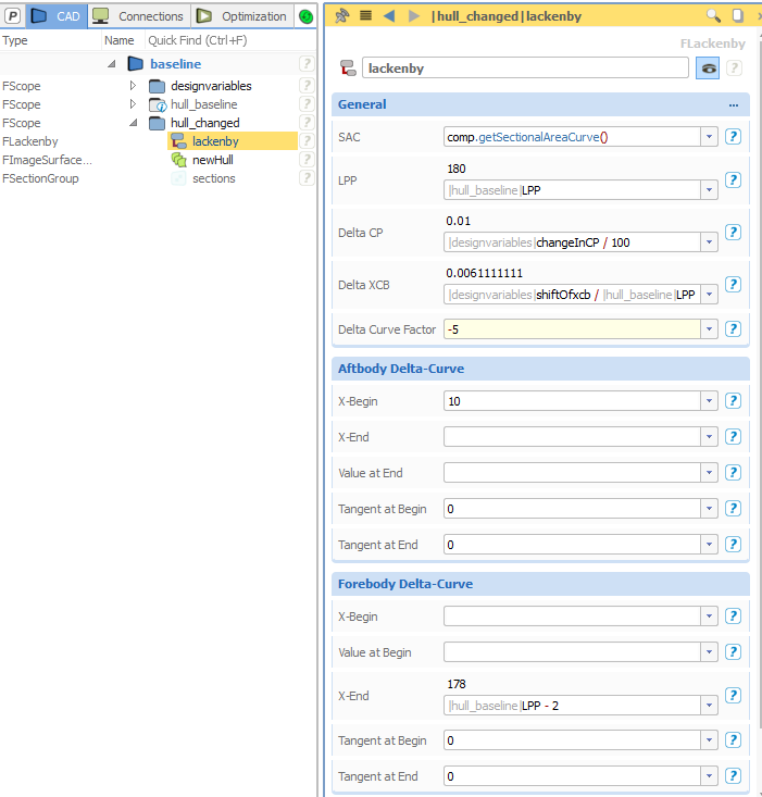
The shift transformation simply takes this initial sectional area curve, plus inputs for the change of displacement and the center of buoyancy. The volume shift is then conducted by applying a smooth shift function in a specific range. In addition, you can optionally control the start and end tangent of this function. These inputs can be set separately for the forebody and the aftbody, respectively. The function curve gets calculated by the Lackenby itself. As a user, you don’t have to care about this detail — this calculation is done internally.
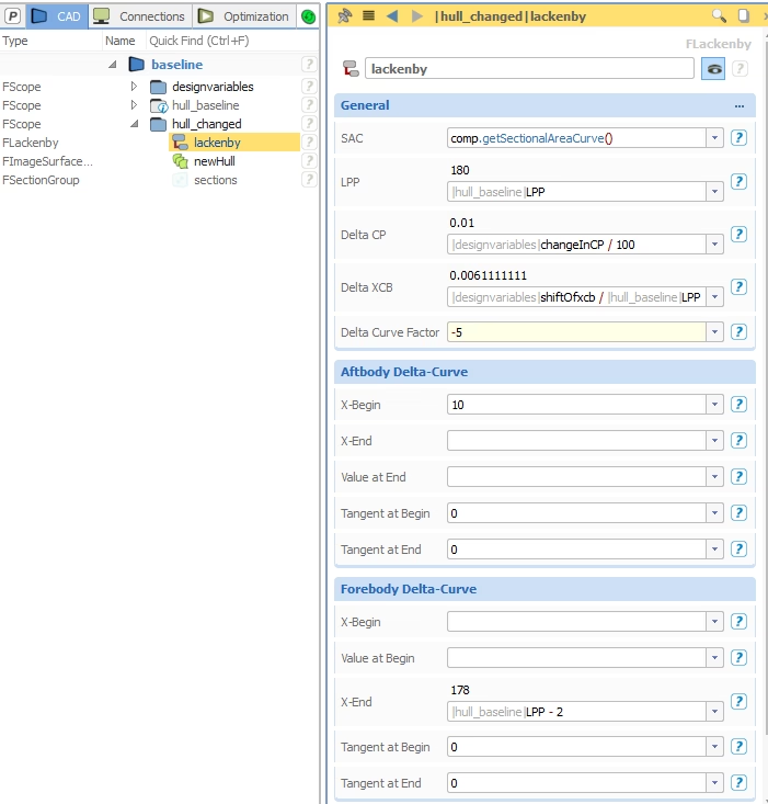
Lackenby setup
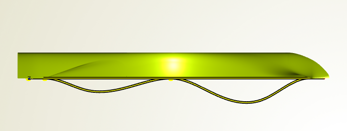
The shift function provides the delta value at a specific x‑position, i.e. y(x) = dx(x). This means, at a specific x‑position of the hull, there is a shift of the geometry in x‑direction by using the corresponding y‑value. A positive y‑value means forward shift, and a negative value a backward shift. The zero-ordinate is defined by the hull’s symmetry plane. When you look from the top, you can see the calculated shift functions — note that they are scaled up by a factor (attribute “Delta Curve Factor” in the screenshot above) for better visualization, the real values are much smaller:
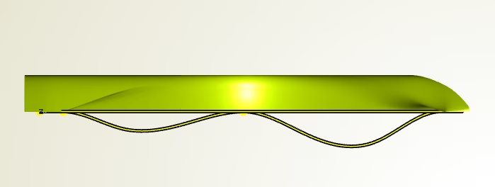
Visualization of shift function
The Modified Hull
In order to apply the shift transformation to the existing geometry, you have to create an image of the hull and set the Generalized Lackenby as transformation. An example is shown below. The x‑sections can be visualized in the display options of a surface, and the color can be set individually in order to have a quick comparison.
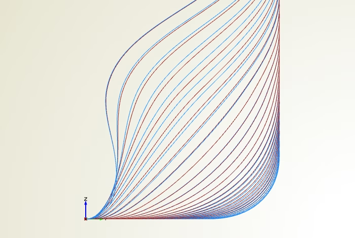
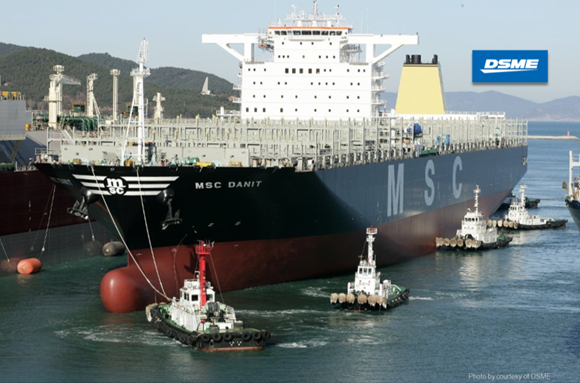
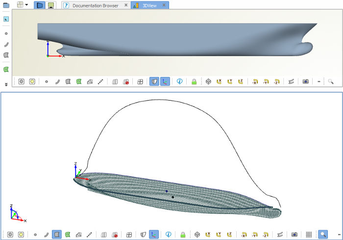
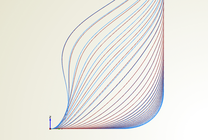
Comparison of initial hull and new shape
More Information
There is a more recent post about a bulker carrier optimization and another about reducing CO2 emissions through the usage of CAESES. Interesting numbers — check them out!
Follow Us
Are you interested in design and shape optimization of ship hull forms? Then stay tuned and sign up for our newsletter to receive short reads like this one here! Don’t worry, we won’t bother you with too many emails. Of course, you can unsubscribe at any time :-)