Novel Approaches for sCO2 Axial Turbine Design
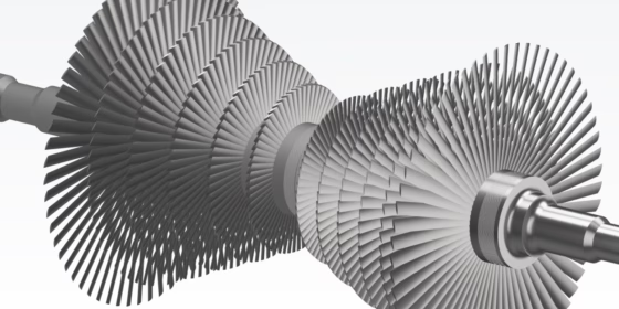
This work on novel approaches for sCO2 axial turbine design was first presented at the ASME Turbo Expo in Phoenix, Arizona on July 17 – 21, 2019.
Introduction
Conventional power plant cycles produce power from turbines using steam as the working fluid. Supercritical carbon dioxide (sCO2) cycles use CO2 in a state where temperatures and pressures are above a critical point – the supercritical state. In this state CO2 exhibits properties in between gas and liquid and has high density and volumetric heat capacity, which gives great potential for higher cycle efficiency. Since the working fluid is more energy dense, the size of components such as axial turbines can be reduced, leading to a smaller footprint and lower costs. sCO2 is also considered to be a safe, abundant, and cost effective medium. Thus, sCO2 power plants have the potential to replace steam power plants from both efficiency and cost perspectives.
The present work explores novel sCO2 axial turbine designs for waste heat recovery (WHR) applications based on a 10 MW case study. A Kulfan Class Shape Transformation (CST) for 2D axial blade profile design is employed, and considerations are undertaken for aerodynamic efficiency and mechanical stresses.
Axial Turbine Design Philosophy
Starting with specifications for size, capacity, operating conditions, etc. an in-house tool developed at Triveni Turbines for 1D meanline calculations was used. The results of the meanline calculation form the basis for 2D blade profile design. The present study uses a 50% reaction turbine aerodynamic design and the flow regime is subsonic.
CAESES is used for the geometric modeling of the axial turbine and the 2D/quasi-3D flow solver MISES is used for the simulations. Within the CAESES environment, an IISc in-house Matlab script is used for pre-/post-processing. The CAESES automation and optimization platform encapsulates the entire process, to optimize for aerodynamic profile losses.
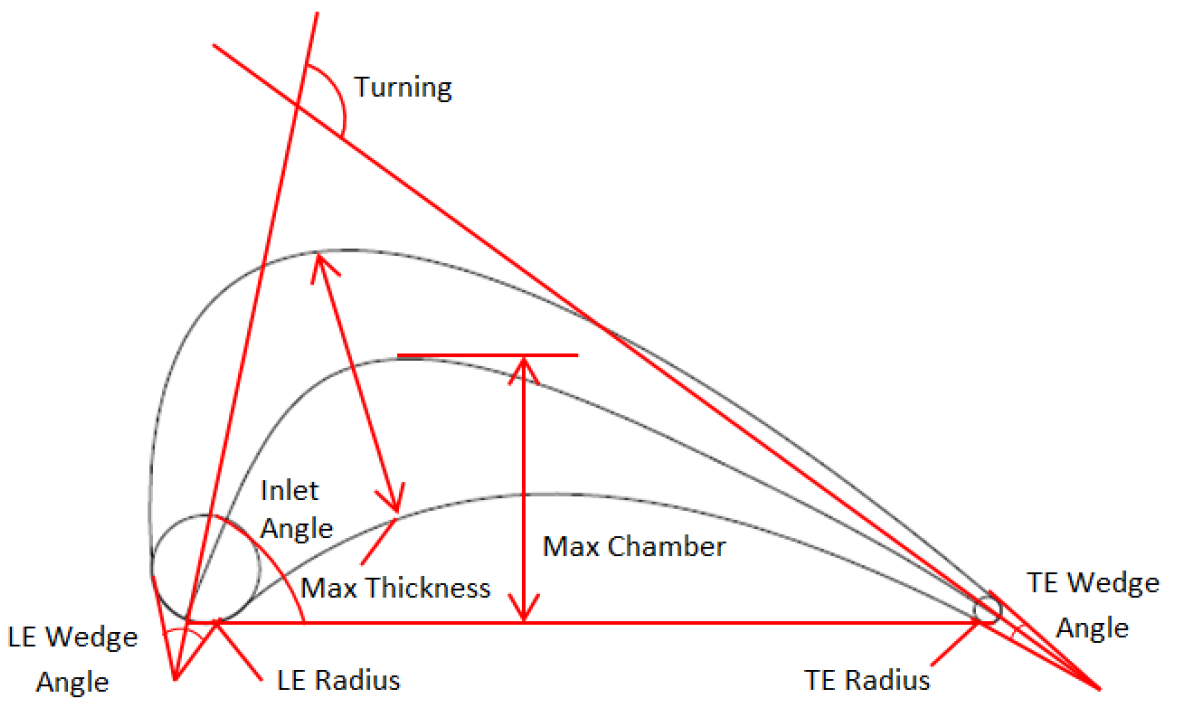
Several approaches are available for parameterizing axial turbine airfoils. A common method is shown in the following figure, which allows the direct control of meaningful parameters such as flow and wedge angles, radii, thickness, etc. However, this approach has limitations regarding the flexibility of geometric variations, making it difficult to explore more novel concepts. Other methods for example are B‑spline curves defined by a set of control points and CST. These approaches lead to greater flexibility and local shape control, which can lead to new and unexpected designs in the optimization process.
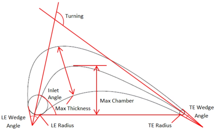
Parametric Definition of a Turbine Airfoil
The present study used a workflow for parameterization, simulation, and optimization based on geometries utilizing B‑spline and CST approaches. The following steps were taken:
- Import 2D baseline profile
- Splitting the baseline into pressure and suction sides
- Automatically fitting pressure and suction sides with B‑spline and CST
- Assigning local coordinate systems to the B‑spline control points to move them normal to the baseline profile
- Applying another local coordinate system for the B‑spline leading edge tangent points on pressure and suction sides to move these points tangentially and change the inlet wedge angle
- Creating geometrical constraints such as inscribed profile area and monotonicity of curvature in certain areas
- Creating design variables for the displacement of control points and CST parameters
- Setting up the software connection which exports the profile to a Matlab script which in turn runs MISES
- Using the DAKOTA global optimization engine within CAESES to minimize airfoil profile loss
Feature definitions created in CAESES automate steps 1 to 7, and specific user defined features were created for B‑spline and CST based airfoil design optimizations.
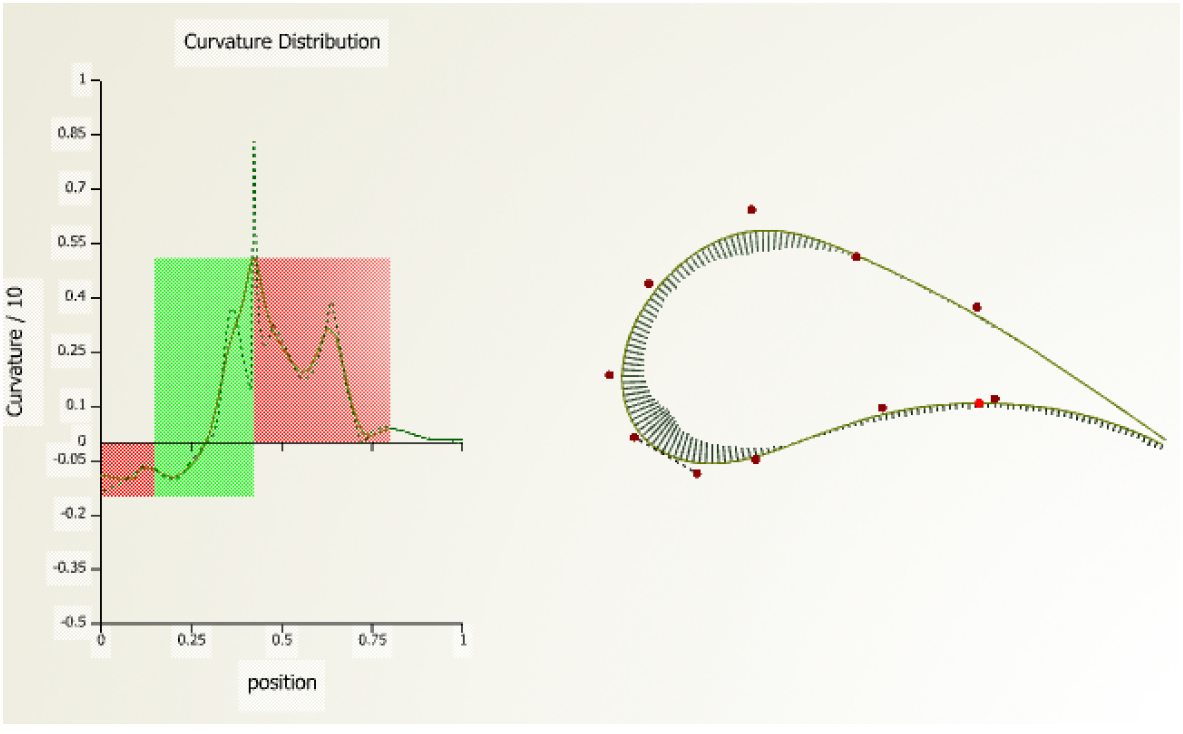
Surface curvature has a major influence on pressure distributions for subsonic airfoils. A unique curvature identification feature was created in CAESES and applied as a constraint to have a reasonable number of parameters and to ensure flexibility, while keeping the curvature distributions reasonably smooth.
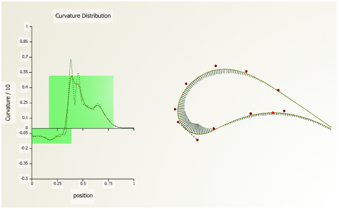
The following figure shows the curvature distribution from the fitted baseline profile where position‑0 represents the trailing edge of the pressure surface and position‑1 represents the trailing edge of the suction surface. A fairing routine is used to smooth the curvature distributions (for B‑splines only). Monotonicity of the curvature is estimated through the derivative of the curvature distribution.
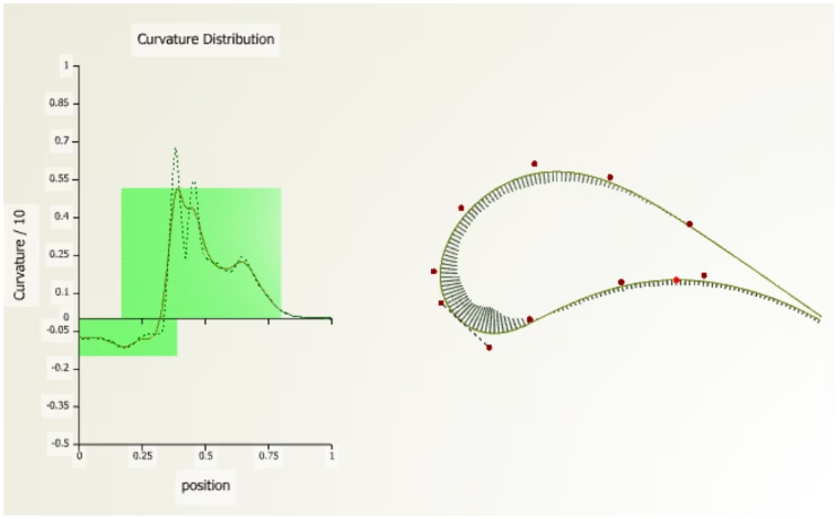
Airfoil surface monotonous curvature distribution
The curvature analysis is divided into separate zones around the profile, and constraints are set up which judge the monotonicity of these zones. A tolerance is set up to allow for small non-monotonous fluctuations. The following figure shows an example for a violated curvature constraint (shown in red).
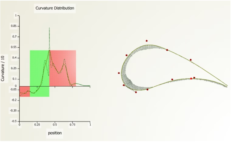
Airfoil surface with non-monotonous curvature distribution
Aerodynamic Optimization of Axial Turbine Blades
The turbine airfoils have been optimized to minimize profile losses. Separate optimizations were performed for the B‑spline and CST geometric parameterization methods by assigning design variables for the control points and CST parameters respectively. Curvature monotonicity was set as the constraint. The DAKOTA surrogate-based optimization method within CAESES was used. The profile loss coefficient Y2‑norm is defined as the normalized profile loss and is the ratio of each individual run’s profile loss divided by the baseline profile loss. Both the B‑spline and CST methods had a similar number of design variables and constraints and each parameterization method involved 60 iterations.
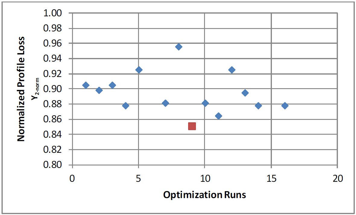
The normalized profile losses for the feasible designs from the B‑spline method are shown below. The range of variation of each control point is 0.05 mm from the baseline value. The design with minimum profile loss was Y2‑norm = 0.85, which means a 15% profile loss reduction compared to the baseline.
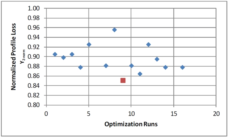
Normalized profile loss for B-spline optimization
For the CST method, the parameter variation is in excess of 70% where the change in geometry is spread over the entire surface. As shown in the following figure, the optimization found a minimum normalized profile loss of Y2‑norm = 0.83, indicating a 17% improvement in profile loss relative to the baseline. The CST method was able to cover 40 feasible designs compared to 15 for the B‑spline method, and thus included more of the design space. The best CST design was 2% better in terms of profile losses compared to the best B‑spline design.
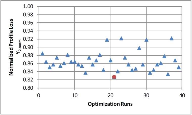
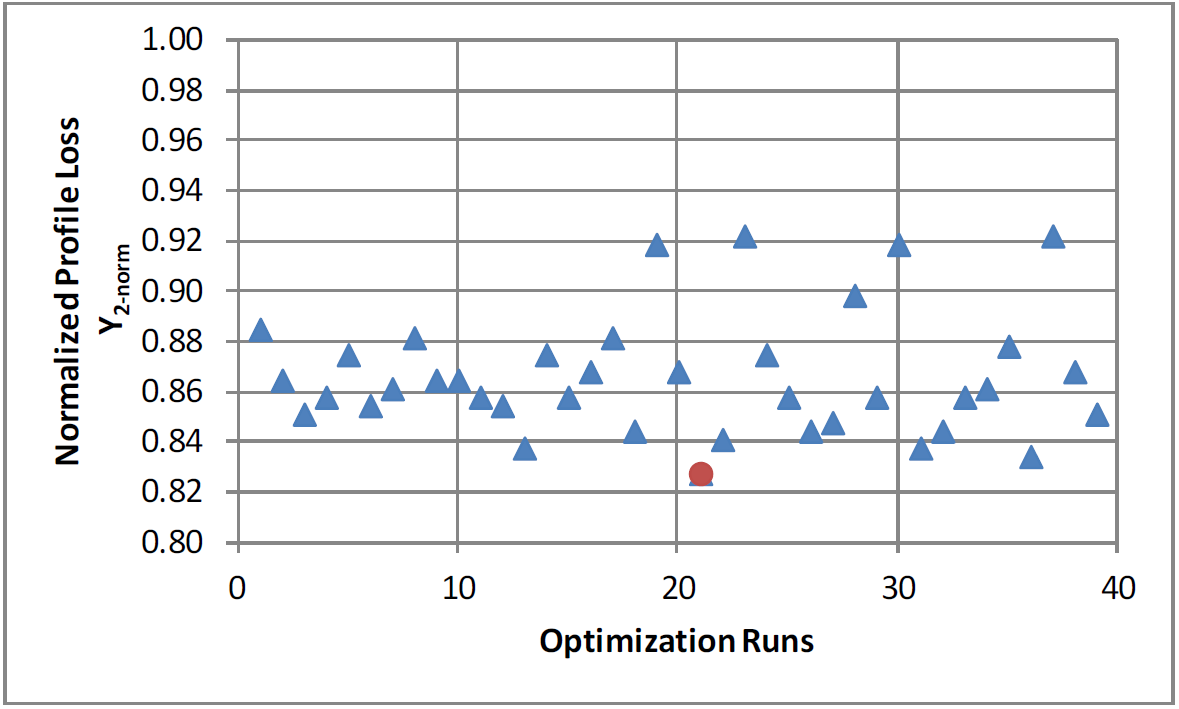
Normalized profile loss for the CST optimization
Further Considerations
The project also considered blade stress calculations which form an integral part for the design of turbine blades, especially for high energy density sCO2 cycles. Calculations for blade static stress as a summation of the centrifugal tensile stress and the bending stress due to fluid loading were undertaken.
Studies were also carried out to understand the effects of increased power density on the turbine design when scaling from a 10 MW application to as much as 50 MW. Changes in operating conditions, blade sizing, and blade materials were considered in the scalability study.
Conclusions
The present study on the design of axial turbine blades for sCO2 turbines used for waste heat recovery applications has illustrated the use of novel parameterization methods and automated optimizations in an effort to investigate novel designs that exhibit substantially lower profile losses and hence higher efficiencies.
The B‑spline based parameterization gave a design with 15% reduction in profile loss compared to the baseline. The class shape transformation (CST) technique yielded even better results with a 17% reduction in profile losses compared to the baseline (i.e. 2% better than then the best B‑spline design).
Acknowledgement
We would like to thank the following authors for their contribution to the paper which forms the basis for this technical blog post.
Lead author:
Sharath Sathish, Indian Institute of Science, Bangalore, India
Contributors:
Pramod Kumar, Indian Institute of Science, Bangalore, India
Adi Narayana Namburi, Triveni Turbines, Bangalore, India
Lokesh Swami, Triveni Turbines, Bangalore, India
Pramod Chandra Gopi, Triveni Turbines, Bangalore, India
Carsten Fuetterer, FRIENDSHIP SYSTEMS AG, Potsdam, Germany
For Further Information
The full paper can be downloaded from the ASME digital collection portal for $25.00.
Novel Approaches for sCO2 Axial Turbine Design
Proceedings of ASME Turbo Expo 2019: Turbine Technical Conference and Exposition
GT2019-90606