CFD Optimization Software: 5 Tips for Selecting the Right One
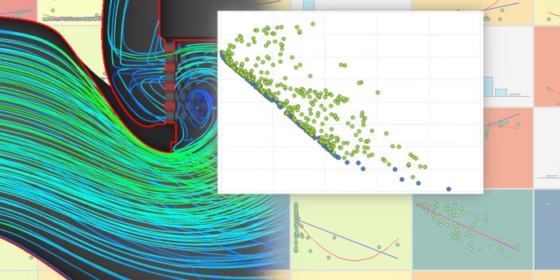
When we talk about CFD optimization software, we actually think of an entirely automated engineering process that covers geometry generation, meshing, simulation, and design post-processing. All of these single steps are automated to create a closed optimization loop where, finally, the optimal design candidate(s) emerge from the process, showing optimal results in terms of the product’s flow behavior (e.g. minimum pressure loss, lowest drag, reduced wave resistance, flow homogeneity, robustness for different operating conditions, etc.).
Naturally, setting up such a CFD-driven process requires expertise in the application itself but also in various CAE disciplines, i.e., the engineers need to be familiar with the use of different CFD and optimization software packages. Here are 5 quick tips that will help you to select the right CAE solution for your CFD-based optimization task:
Tip #1: Focus on Robustness of the CFD Optimization Software
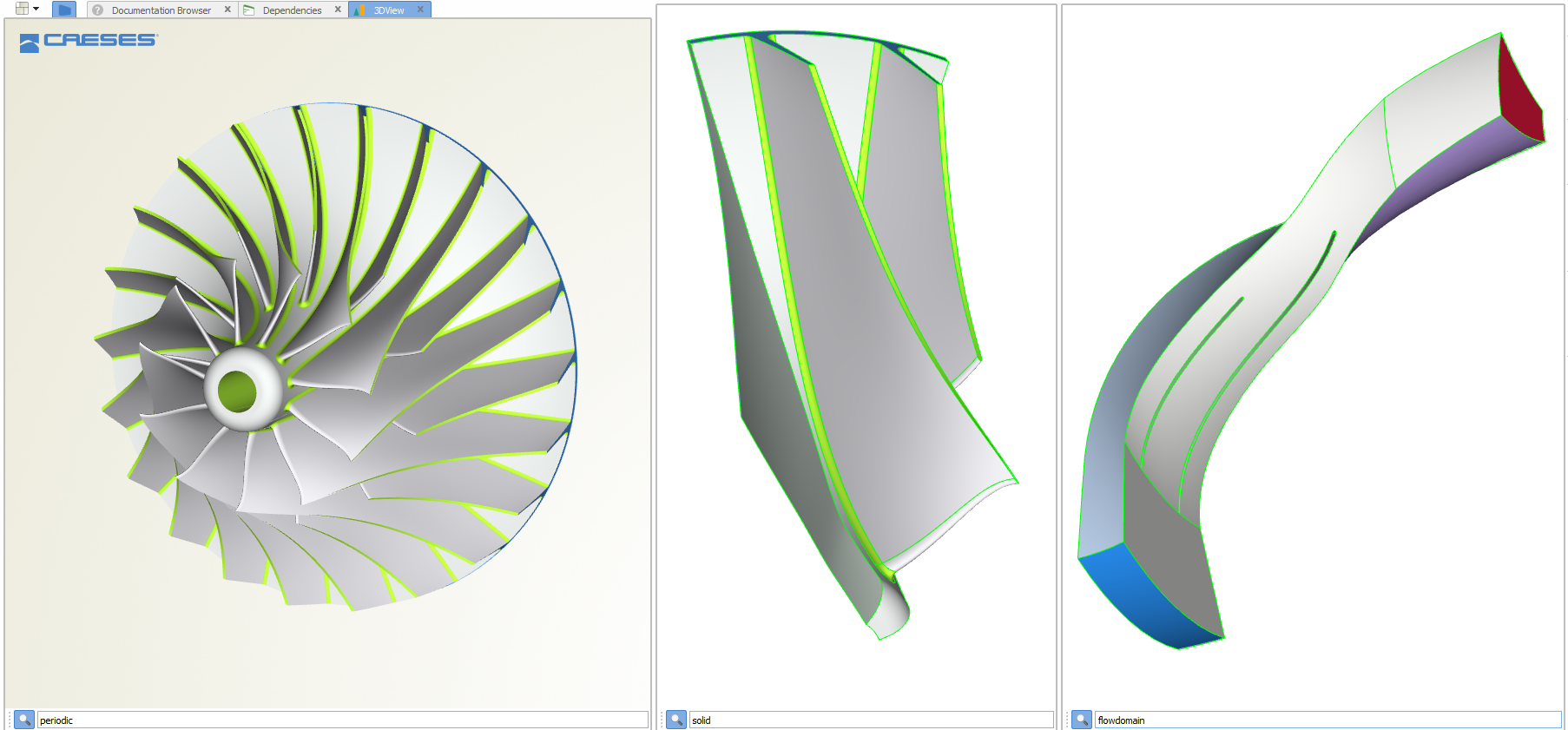
The involved CAD and simulation software tools need to be robust for automating them. In particular, the geometry generation of new design candidates should not fail. Ideally, it should create only feasible designs that do not violate given geometry constraints. If your geometry model can keep track of this, you will save a lot of time and manual interaction. Many tools on the market are not directly suited for automated batch runs (i.e., non-GUI runs without manual interaction). Trying to automate them can be a tedious and, in the end, very expensive task on your way to a working optimization loop.
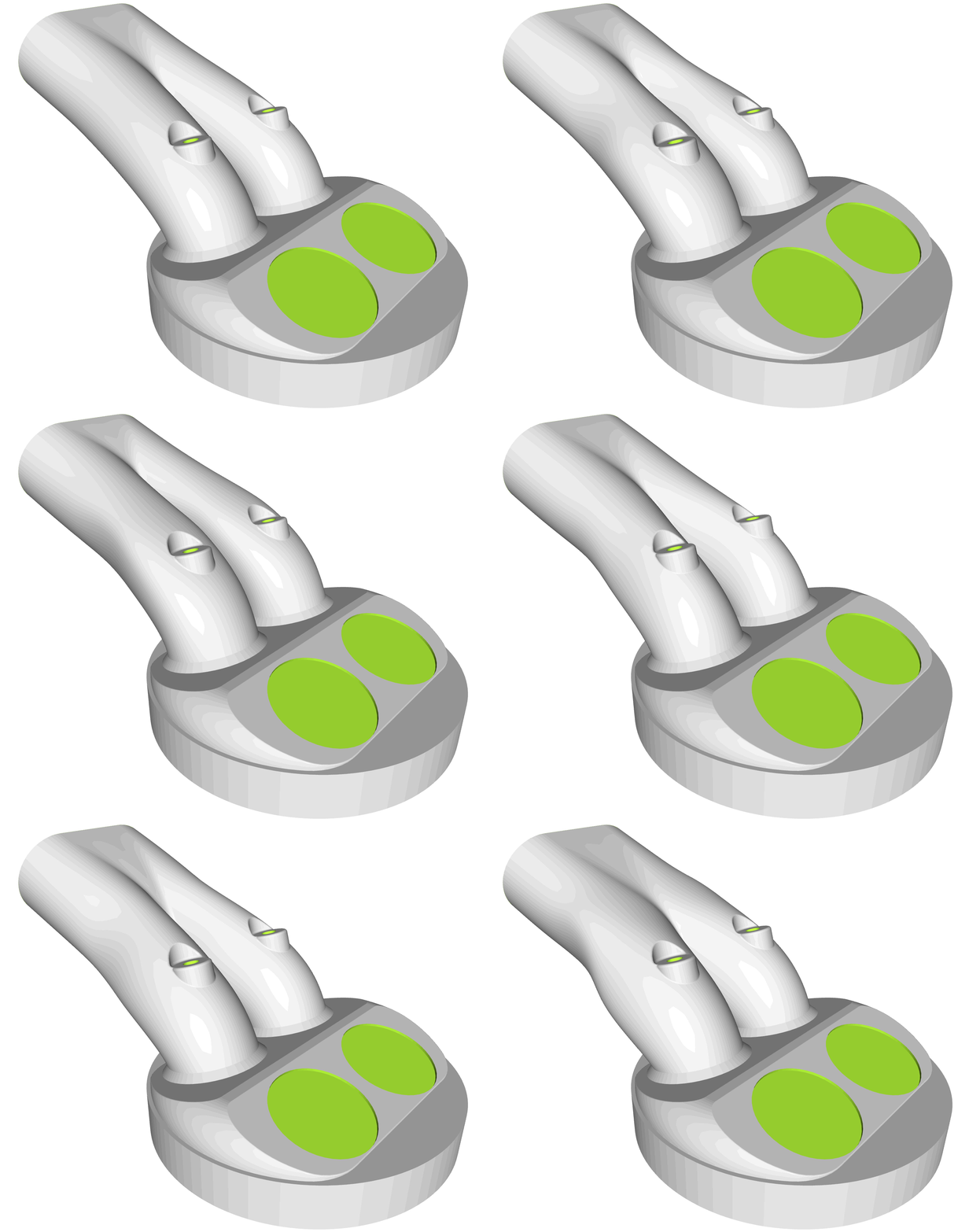
CFD optimization software: Robust automated geometry variation of an intake port
Tip #2: Demand Flexibility
The optimization projects you work on now can be very different from the ones you will work on in the future. This is not only due to the variety of components that can be found in companies that need optimization, but also due to the degrees of freedom available for exploring and discovering innovative product ideas. When you start doing CFD-driven shape optimization, at some stage, you will encounter the wish for more parameters and higher flexibility, while also requiring highly efficient procedures. Hence, your optimization loop should be flexible in terms of the application, no matter if you have a highly specialized complex task or a simple optimization problem.
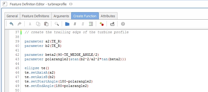
Scripting capabilities of CAE tools are important for customization
For instance, the tools you select should come with comprehensive possibilities for customization, such as scripting and programming capabilities. From our experience at FRIENDSHIP SYSTEMS, we can observe that flexibility through scripting is absolutely essential for creating the most competitive products on the market. So, make sure your software choice considers long-term developments in your company by providing high flexibility.
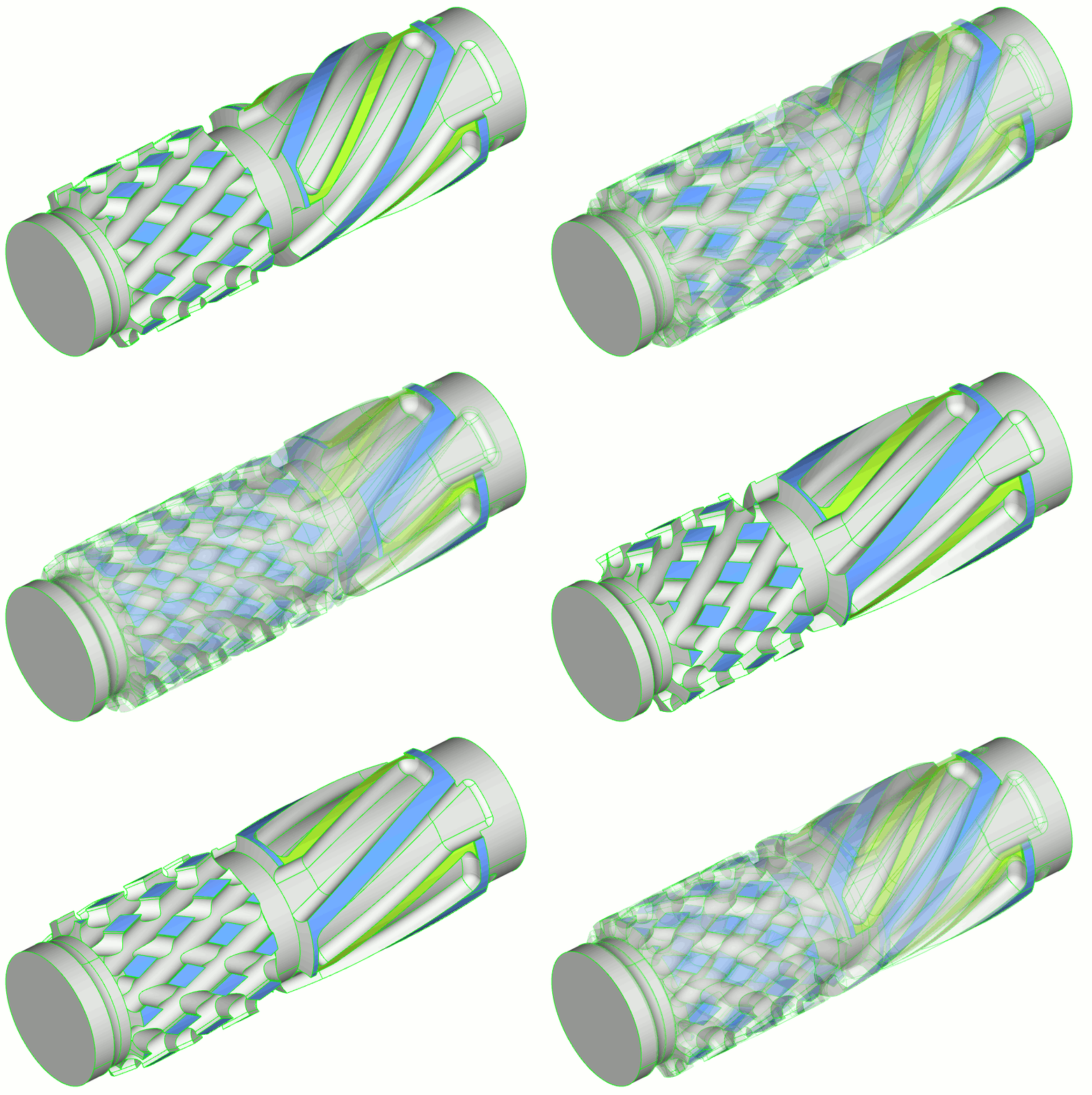
Robust variable geometry for design studies, where complex features can be additionally scripted and customized
Tip #3: Use CFD Optimization Software from Experts
Probably, you will first check whether your existing tools can be part of your optimization workflow so that no additional expertise or software is required. For instance, for a subset of optimization tasks, traditional CAD tools such as Catia, NX or PTC Creo can be automated and used in the optimization loop.
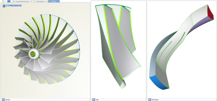
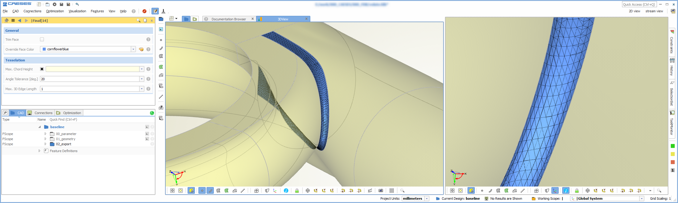
The expert software CAESES includes features for CFD-driven optimization such as parametric fluid and structural domains
However, for more sophisticated optimization tasks, it might make sense to check dedicated software packages, such as CAESES. If you are designing complex products, where the automation of geometry generation and CFD simulation is challenging, you should consider software that already solves many of the typical bottlenecks, e.g. robustness issues during variation and details such as keeping the face IDs.
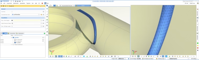
Assign color and triangulation settings for each individual surface patch that is then robustly preserved for all generated variants
Since you are combining several different CAE tools in a CFD-driven process, your selected tools should also smoothly work together from a technical point of view. Vendors of CFD optimization software often have partnerships, to make sure the tools work together without any issues (e.g. data exchange between CAD and meshing tools).
Besides, take a look at the team behind the software that you license: What are their expertise and their absolute focus? Can they be a good partner? What about their support, how fast is it? Which complementing services are offered to accelerate your work on your very specific optimization task? Finding a good and specialized partner will be important in the long run, and will create value and benefits for both parties.
Tip #4: Think about Your Geometry Optimization Approach
Generally, you have a choice between parametric CAD, morphing and deformation, topology optimization — also to utilize other approaches such as adjoint CFD techniques. Let’s take a quick look at these:
Parametric Models
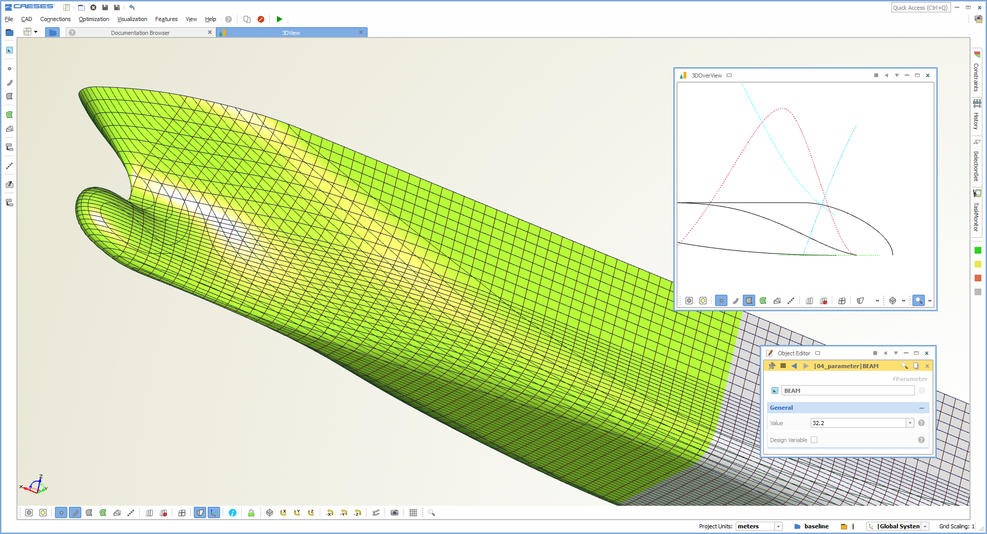
If you want to control your shape through a parameter set that is naturally connected to typical properties of your product, you would pick a parametric CAD tool. For instance, turbine or ship hull designers typically create their geometries based on a parametric description, that contains items such as profile parameters, chord lengths, contour curves, displacement functions, etc. In these cases, you will create and work with a fully parametric model that provides direct controls for all the properties you need. These controls can then be linked to the optimization tools or the integrated sampling and DoE strategies.
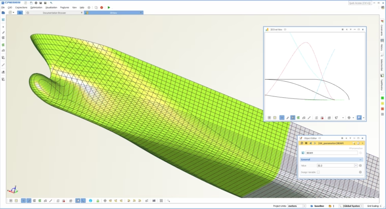
Parametric CAD as one option for CFD engineers
Morphing and Deformation
If the parameterization itself is not important, you can evaluate morphing and deformation tools as your CFD optimization software. Changing the geometry is done through deformation boxes or radial basis functions (RBF), for instance. This allows you to quickly define some degree of geometry variation and therefore, to optimize a product in a shorter period because you do not need to invest the time for creating a parametric model upfront. Instead, you work on imported, i.e., existing or already meshed geometries. With morphing techniques, you will have limited flexibility and direct control. You will have to somehow ensure that you create only feasible designs and useful geometries (e.g not highly squeezed surfaces or meshes, considering space constraints, thicknesses, distances, etc.). Also, if you are morphing meshed geometries, you might have to consider how to bring your optimized shape back into CAD at the end of the process.
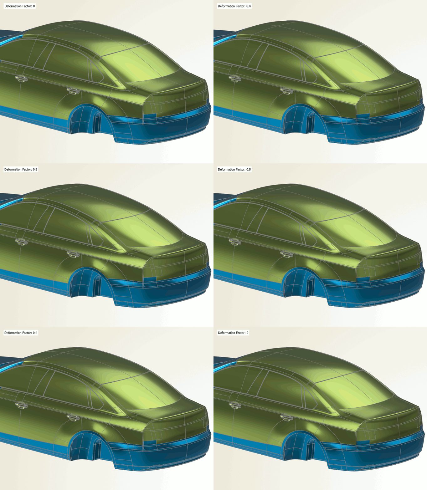
Morphing as part of CFD optimization software
Adjoint CFD
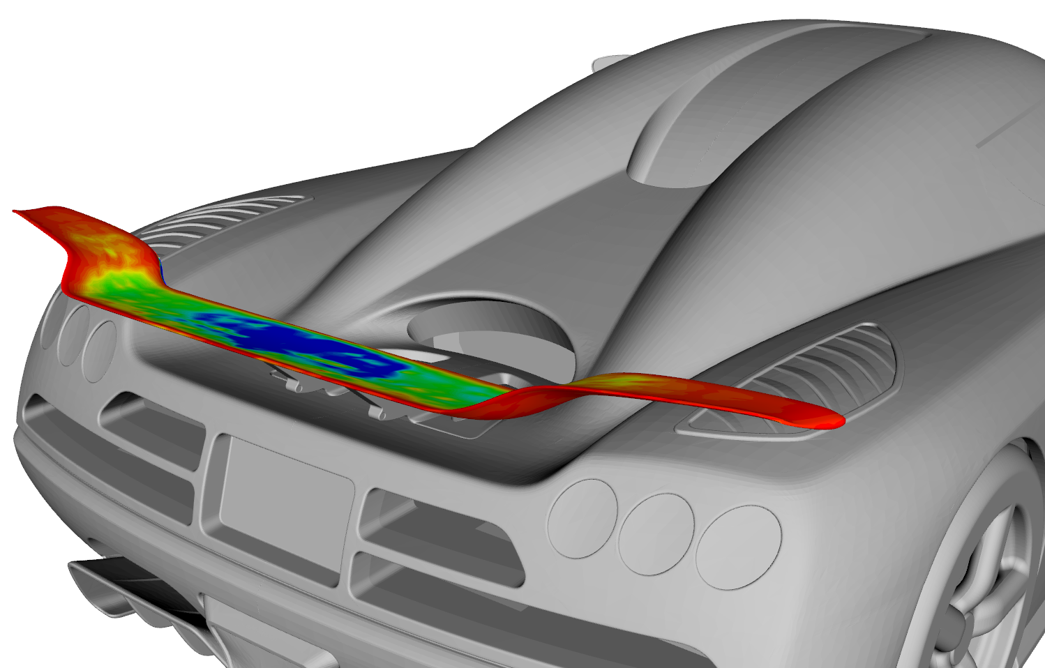
There is also the field of adjoint CFD, which might be of interest if you are dealing with a high number of parameters and rather expensive CFD computations. If your CFD tool offers an adjoint solver, you will just need one additional calculation to find out how the different areas of your geometry influence the chosen objective. These so-called shape sensitivities can be directly used for morphing the geometry, or you can connect your parametric CAD model to the adjoint solution. By mapping the shape sensitivities to the geometry parameters, you can quickly identify the most influential parameters and significantly speed up the optimization process.
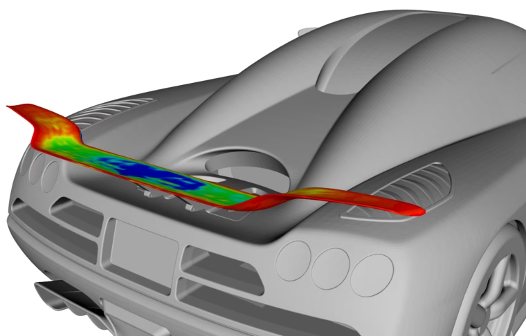
Adjoint sensitivities on the rear wing that can be coupled to the CAD model
Topology Optimization
Finally, there is also a broad field of topology optimization, which is suitable for generating ideas very early in the design process. This approach does not require a parametric model or any deformations to be set up. Based on a definition of the available space, it takes into account physical constraints, such as forces that act on a component or inlet/outlet conditions, and automatically evolves to an optimal geometry shape. Here, a challenging task is often to convert the resulting geometry to a reasonable NURBS representation for manufacturing purposes.
Tip #5: Check Value vs. License Costs
There are probably optimization tasks that can be carried out manually with sufficient results and where the added value of a highly optimized product is not balancing the investments of new CFD optimization software.
Commercial Packages
However, and since you are reading this article, you probably have a design task that needs optimization. If your company or department is currently struggling with a budget for commercial CAE tools, there is one thing you can do: Open Excel and try to calculate the benefit — in Dollars or Euros, or another competitive advantage — when being successful with the tools! Assume a product improvement of 3%, 5% or 10% (whatever you want to achieve or is realistic) and write down how your company and your customers benefit from it.
Also, think about the engineering time that you would be able to save by automating the process of creating geometry variants and evaluating them. In most cases, a simple calculation can show you the real value you obtain from efficient CAE tools. If you are not sure about the benefit, sit together with the selected software vendors and try to jot it down. The key stakeholders of your company must have a clear idea of the value when investing in software.
Open-Source Software
Finally, if you have a very strong niche or product focus, as well as enough human resources to explore software capabilities on your own, an open-source software might be an option, too. Examples are OpenFOAM, Python packages or the Dakota tool kit, for which CAESES offers an integration in the context of using response surfaces.
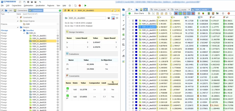
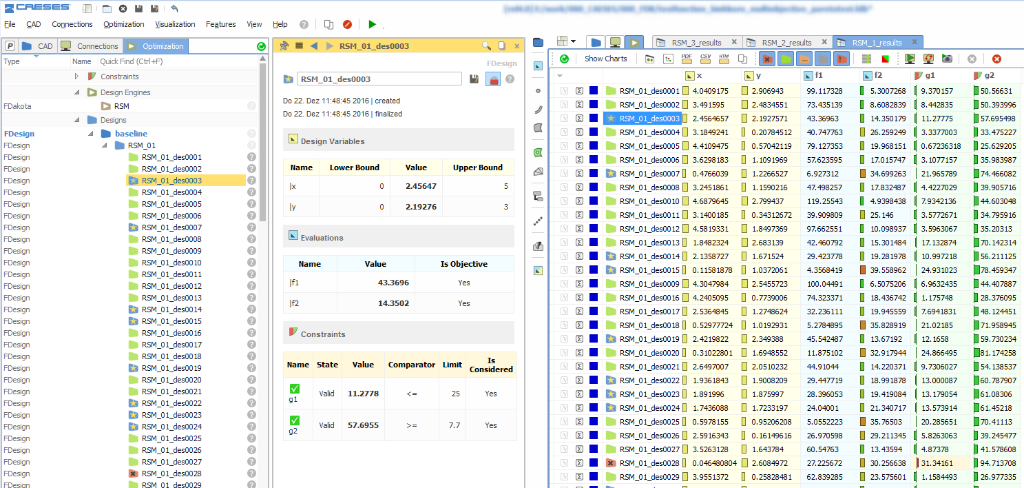
Design and variant management in CAESES, based on the Dakota toolkit
List of CFD Optimization Software
To wrap up this article, here are a few selected tools, where we know that the CFD optimization software packages are well suited for automated processes. Theses solutions can be linked to each other, and there are some partnerships between the different vendors, to ensure a streamlined data exchange within the toolchains. For automating the geometry generation, there are also integrations (add-ons or plug-ins) available, to couple CAESES to other platforms and environments such as ANSYS Workbench.
CAD, Morphing, Parametric Adjoints
- CAESES
Meshing
- ANSYS tools
- GridPro
- NUMECA tools
- Pointwise
Optimization
- HEEDS
- ModeFRONTIER
- OptiSLang
- Optimus
- Dakota
Simulation
- ANSYS tools
- Autodesk tools
- CONVERGE
- FLOW-3D
- NUMECA tools
- OpenFOAM
- SHIPFLOW
- SIMERICS tools
- STAR-CCM+
- TCFD
- XFlow
More Information
If you are interested in software for CFD-driven shape optimization, check out the CAESES pages. CAESES is an all-in-one solution for CAD, automation and optimization in the context of complex product design with CFD.
ANSYS Users
For ANSYS users, there is also a CAESES ACT app to run shape optimizations directly within the ANSYS Workbench.
Aerodynamic Blog Post
Check out the article “Aerodynamic Shape Optimization: A Practical Guide” which also covers related issues in the field of aerodynamics.