CFD Flow Domain for Ship Hulls from NAPA IGES Files
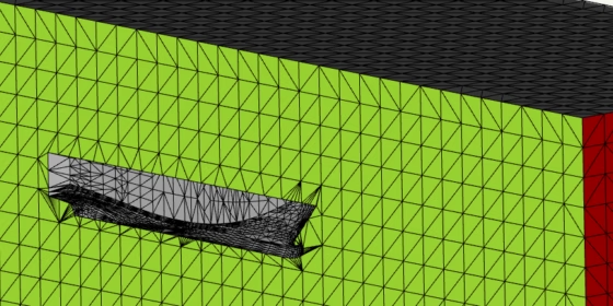
From time to time we receive NAPA IGES files from our maritime customers which are basically an assembly of often hundreds of single surface patches. The question is then: How can we quickly create a watertight, box-like flow domain for these ship hulls that can be readily meshed, for use with tools such as FINE/Marine, STAR-CCM+ or SHIPFLOW?
An example of such a flow domain is shown above in the header picture of this blog post. Since this is in most cases a symmetric shape, only one half of the ship hull body is considered.
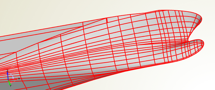
To give you a better idea of what kind of data we are talking about, check out the following picture. It shows a typical NAPA geometry, imported into CAESES®:
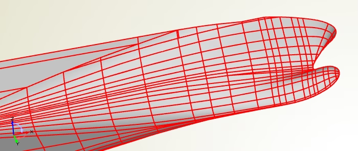
Typical surface patchwork of a ship hull, exported by NAPA and visualized in CAESES
The Challenge
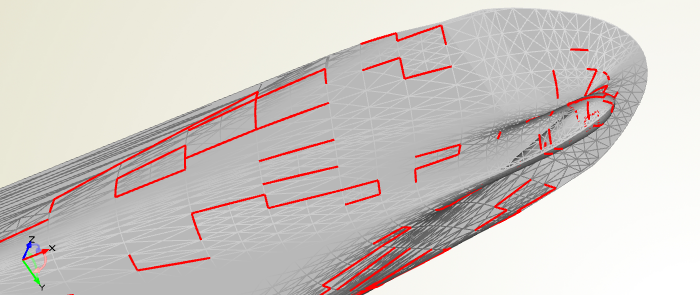
Creating a flow domain from a ship hull body that is perfectly closed (e.g. a solid body or at least a set of exactly adjacent surfaces) is not a big deal — you can simply use a set of Boolean operations. However, in our situation this is not the case: If we look at the tessellation of the surface patches, we can observe that often they do not match exactly at the boundaries. There can be larger gaps between the single surfaces. For many meshing and grid generation systems on the market, these gaps are critical and possibly an automated meshing cannot be realized with this.
The problem: Gaps between the imported surface patches and overlapping surfaces.
Even if we try to apply a fast joining procedure based on our trimesh functionality, the result still shows that some gaps are simply too large.
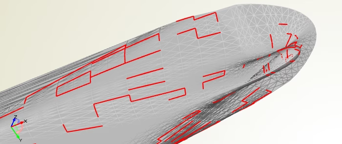
Attempt to automatically join the surface patches with a basic joining procedure
If we further increase the snapping tolerance for joining the surfaces automatically, other tiny surface patches are accidentally joined — so there is some limit to this approach, and it is only applicable if you cope with STL data for meshing (i.e. the surface topology remains the same, only the tessellation is fixed).
We can also zoom into one surface patchwork at the propeller region where the flat of bottom disappears, which is shown in the next picture. From the distance everything looks fine, but using our mouse wheel to zoom in, it suddenly reveals that the surfaces do not correctly meet each other in the corner:
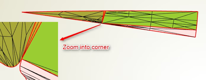
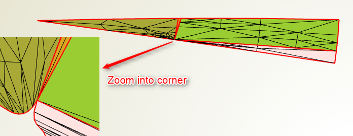
Surfaces do not correctly match in the corner
We have also observed surface patches that are self-overlapping in singularities where the corner vertices should actually meet each other exactly. It can be quite a tedious task to manually repair these surfaces in traditional CAD systems, just to receive a clean surface mesh that can be used for simulation. So we need something that does the job with just a few mouse-clicks.
An Automated Solution
We have recently spent some time to come up with an automated solution in CAESES®. If the input geometry is heavily corrupted in terms of the surface quality, there are also limitations. However, for most of the geometry data that we have received, this automated process works well and appears to be an elegant and fast way to go.
Driven by the NAPA IGES files but also various demo files from other CAD systems (Rhino etc.), we have developed generalized methods to import typical ship hull geometries and apply an intelligent sewing and healing to the unclean BRep topology. This results in a closed surface topology, from which we can generate our target flow domain without any problems.
How It Works
It’s easy to use: You only chooses the IGES file and some color settings for the domain patches, such as the symmetry plane, the hull parts and so forth. This is important for an optional colored STL export, where you want these parts to be stored separately. The following video shows how this process works:
In this video, a feature gets created that does the import and the creation of the flow domain. Optionally, you can switch off the domain creation process and only import the IGES file. Note that the green edges on surfaces represent closed edges in CAESES®, while red edges indicate non-matching or open edges. If you need STL data as a result instead of an IGES or a STEP file, you can additionally specify some accuracy settings to fine-tune the tessellation. The deck and the stern part are additionally separated by using a split-by-angle command.
Download
Download this demo STL file and import it into your meshing system to take a look at it. Thanks to the team from NUMECA Germany for checking our generated files!
More Information
Any feedback to this functionality is highly welcome, we are still testing and improving it. If you have geometry data for testing from any CAD/CAE system including NAPA — perfect, just let us know. We’ll take a look at it, and send you the resulting flow domain in this current testing period. Any other questions? Please don’t hesitate to get in touch with us, also if you are interested in using this functionality or if you have a similar task to solve.
We are still testing this! Send us your example geometry and we create a flow domain for you.
Finally, see the marine section on our website for an overview about what you can do with CAESES® in the context of ship design and hull shape optimization:
Follow Us
Are you interested in CFD-related topics and design optimization? Then stay tuned and sign up for our newsletter to receive short reads like this one here! Don’t worry, we won’t bother you with too many emails. Of course, you can unsubscribe at any time :-)