Water Pump Design: Geometry for a Shrouded Impeller
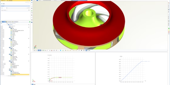
For the CFD-driven shape optimization of water pumps with shrouded impellers, it is crucial to have an efficient variable geometry model with a set of relevant parameters (“design variables”). Let’s briefly illustrate and outline the modeling process of a typical water pump, where the idea is to have full flexibility in terms of shape variations and fine-tuning. The following geometry was set up in CAESES® and all animations were generated in CAESES® by changing all design variables at the same time. Note that the model variations are very large in these animations, to make it easier to understand what’s actually going on (probably designers would not necessarily apply these drastic changes to an initial design).
Meridional Contour
The hub and shroud contours, as well as the leading edge curve, are designed in the ZX-view. Variables are created and connected to these curves (e.g. to the control vertices of the bspline-curves or to an angle control), so that they can be changed in automated processes. Basically, the entire shape can be intuitively controlled and adjusted, if needed.
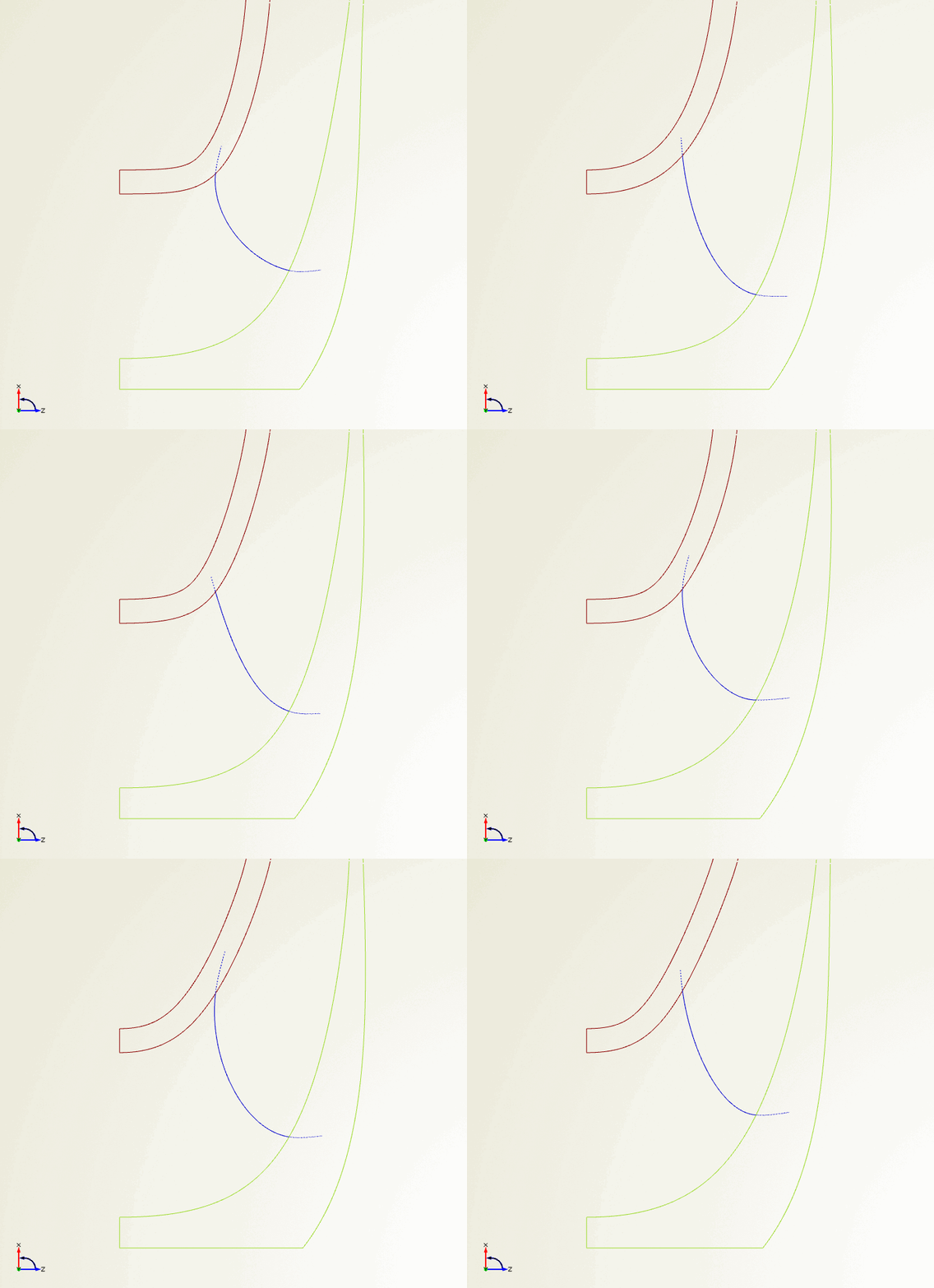
Variation of the meridional contours and casing
Camber and Thickness of the Blade
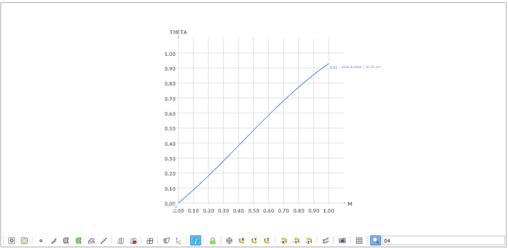
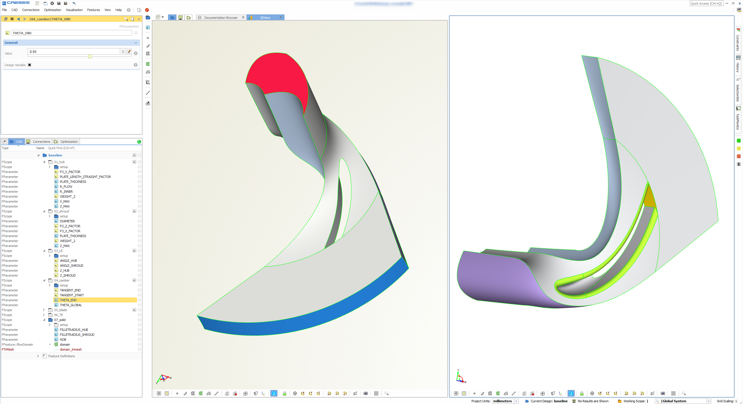
The camber surface of the blade is generated using a theta function in the (m,theta)-system. This function graph is a 2D curve definition for which additional design variables are created and connected. From this function and from the leading edge contour in the meridional plane, one can derive the camber surface.
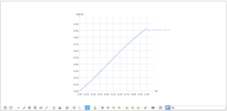
Theta function for generating the camber surface
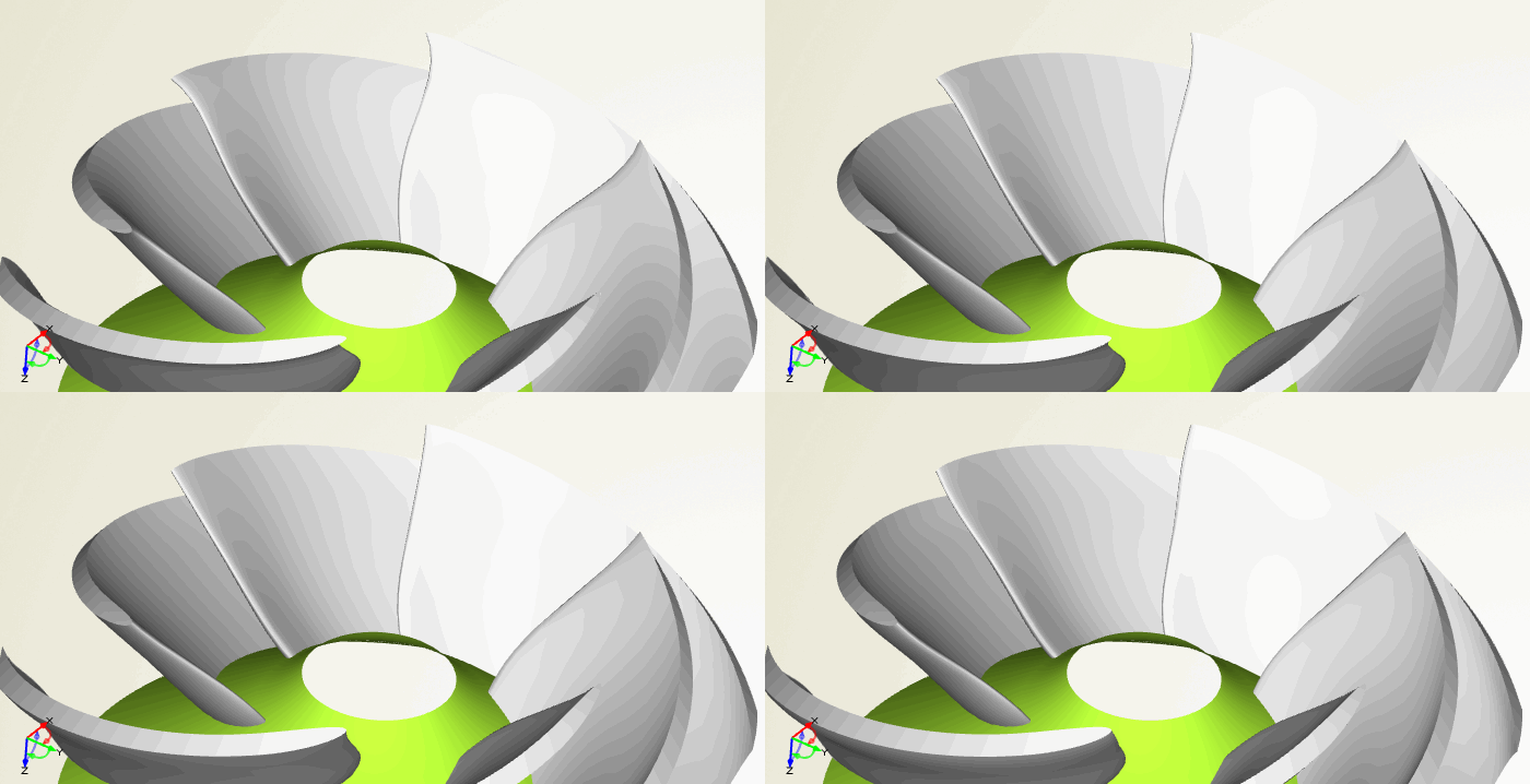
In a next step, the user-defined thickness distribution is applied normal to the generated camber surface. In order to control the shape, additional design variables are introduced to change the leading edge region (more elliptical shapes vs. circular ones) and to vary the thickness from the leading edge to the trailing edge. In addition, the thickness can also be varied in radial direction, i.e. while sweeping from the hub to the shroud.
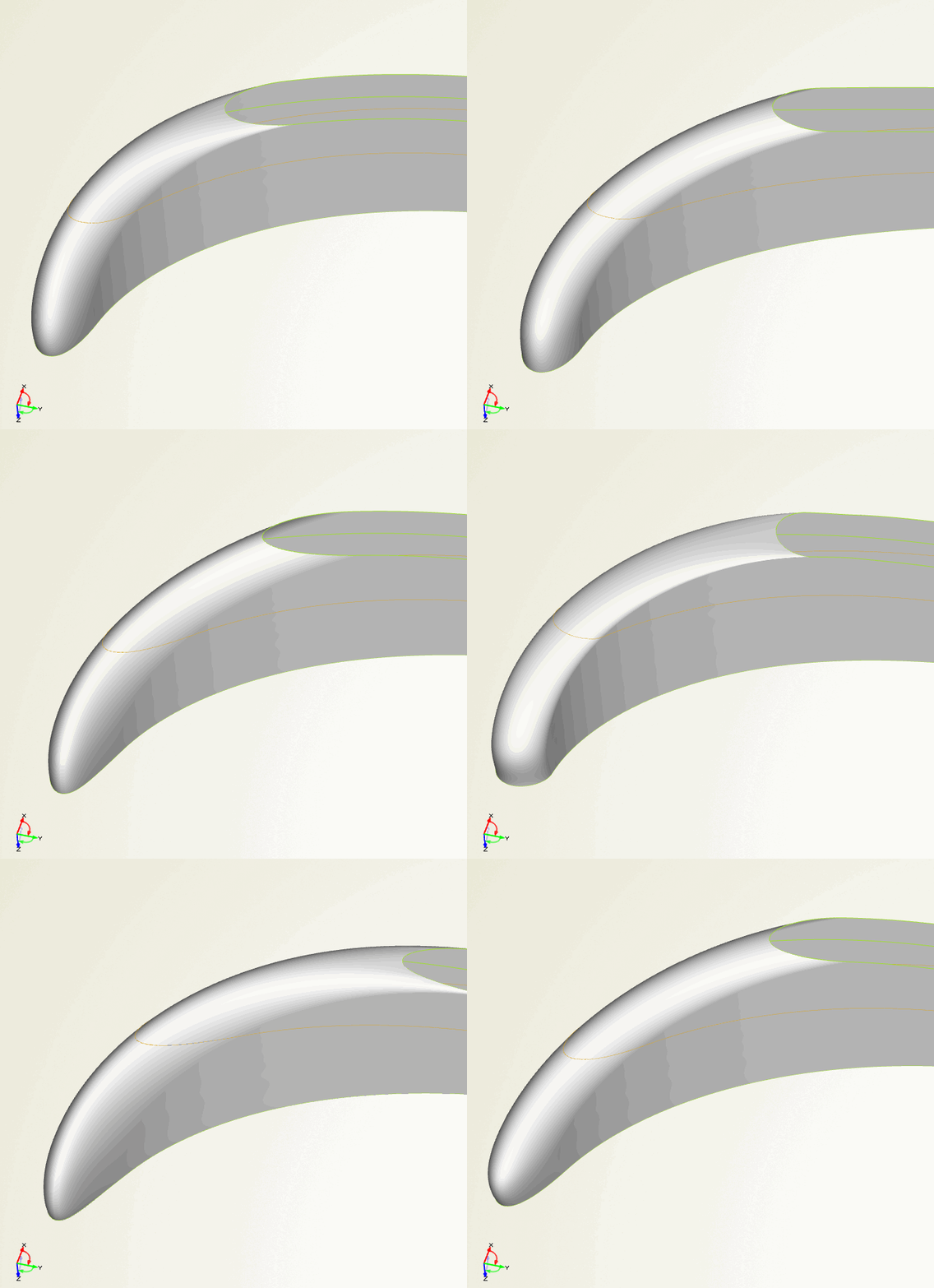
Variation of the impeller blade
Boolean Operations and Filleting
Once the blade surface is generated, it can be combined with the hub and shroud surfaces. In CAESES® we can use Boolean operations to merge these geometries. Fillets are created at the intersection of the blade and the remaining geometry. In our model, there are two fillets (one between blade & hub, and another between blade & shroud). Here is an animation from the top view of the final impeller:
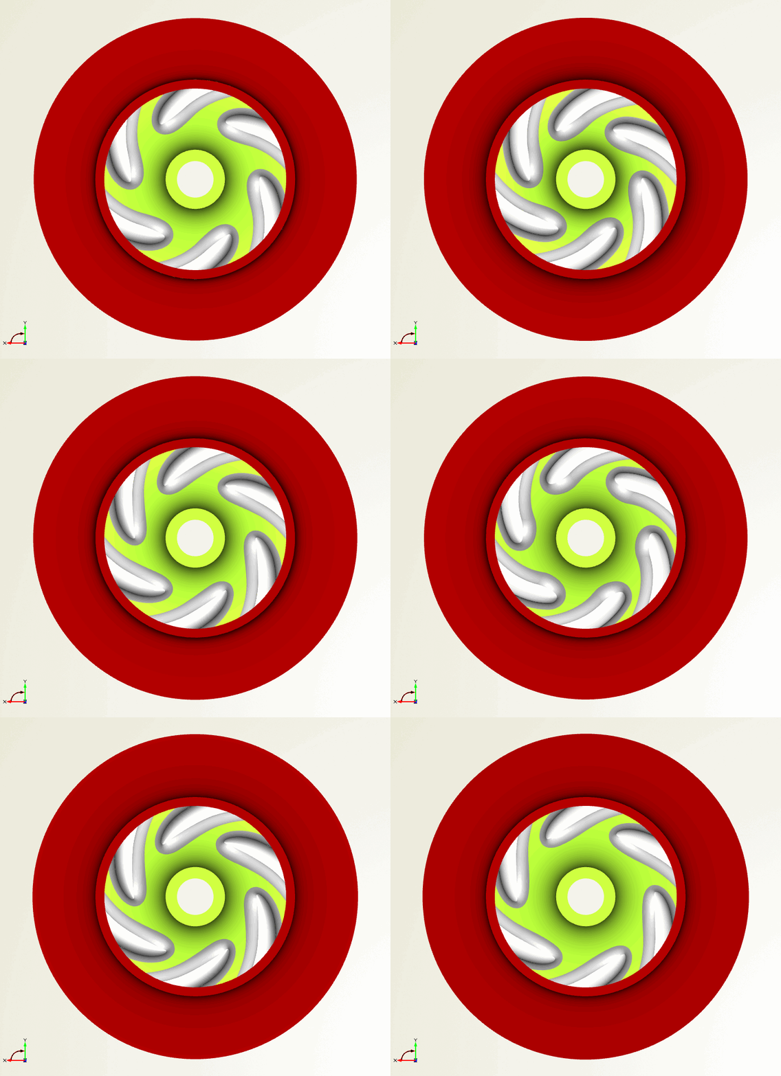
Water pump variation (top view)
And here is a final one, where we zoomed in:
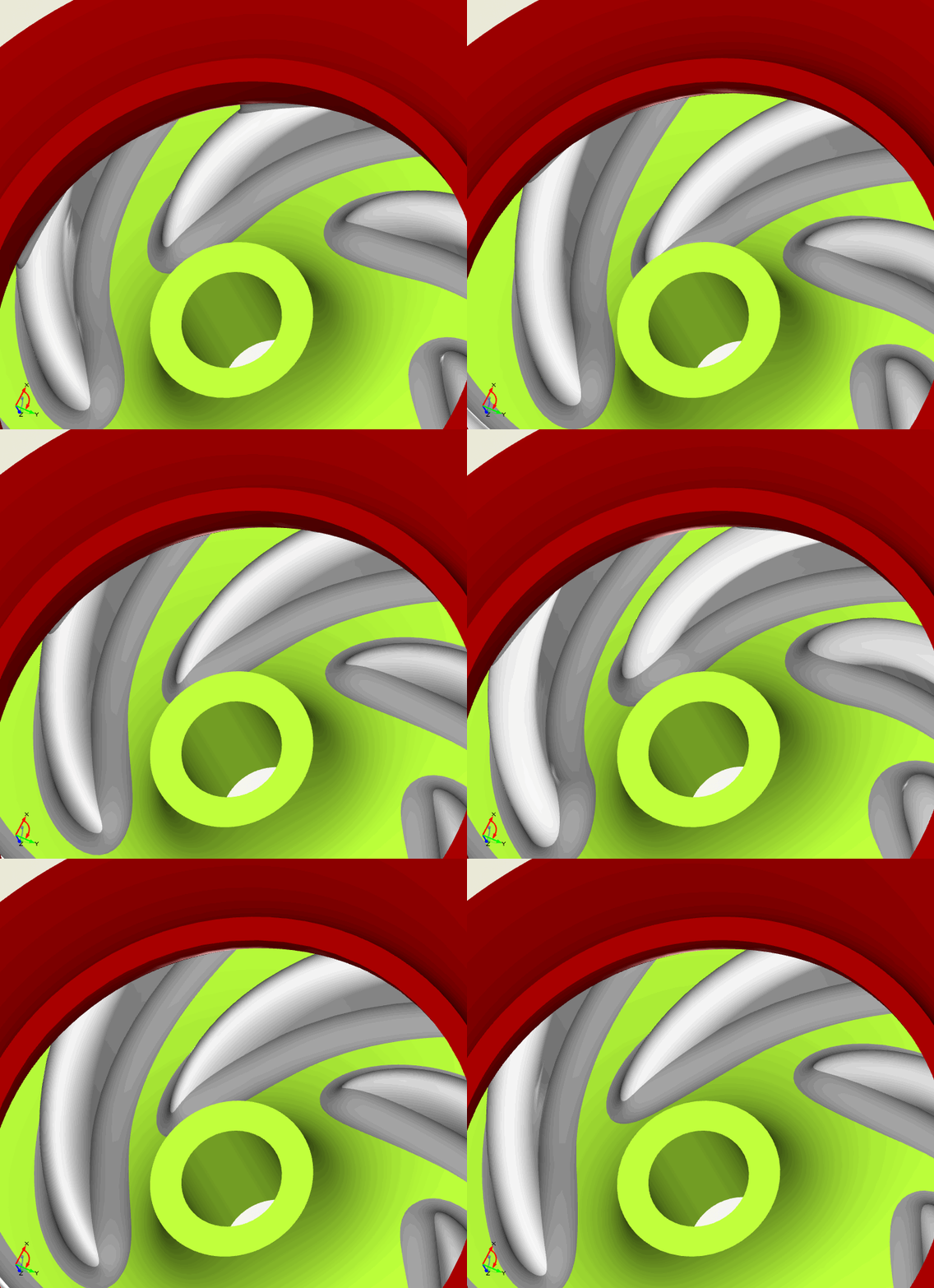
Design and variation of pump impellers
Download PDF Summary
If you are interested in some more details, then check out this PDF summary which contains additional illustrations and more detailed explanations.
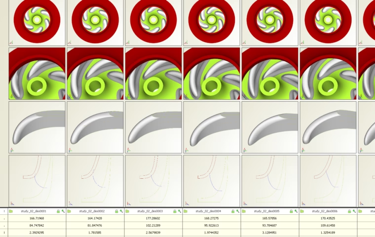
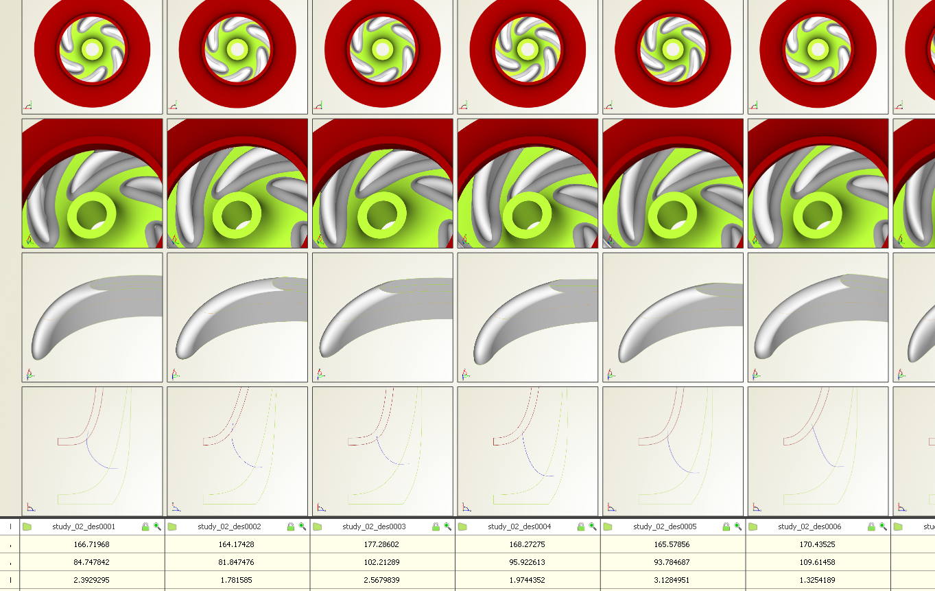
Comparison of design candidates in CAESES
CFD Flow Domain
The parametric flow domain of the impeller can also be automatically derived from the solid model for each design variant. This domain geometry contains several colors for the different patches and allows users to directly automate the downstream meshing process.
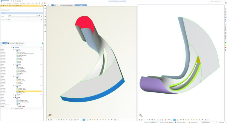
Parametric flow domain of impeller for automated meshing
Download Colored STL Example
The surface patches of the solid impeller are also colored differently, again to make it easy to reference them and automate the meshing process. During the automated variation and optimization, these patch identifiers are fixed and hence the meshing is robust for each new design candidate. Click here to download a zipped STL example of the pump that was generated from the geometry model in this blog post. The file comes as a multi-body STL, and the identifiers are created by using the different patch color information. If you want to take a look at it, just import it into your meshing or CAE package using a standard STL import routine.
More Information
General details about pump design and optimization with CAESES® can be found on the pumps page.
Automate geometry generation for any type of pump impellers
Follow Us
Are you interested in the design and optimization of impellers and pumps? Then stay tuned and sign up for our newsletter to receive short reads like this one here! Don’t worry, we won’t bother you with too many emails. Of course, you can unsubscribe at any time :-)