Released CAESES 4.3
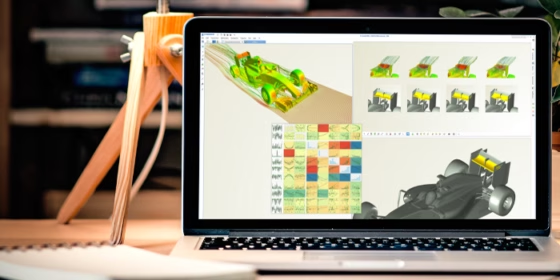
With CAESES® we strive to provide you with the most robust and reliable CAD solution for automated simulation studies. In this first 2018 release, the internal geometry engine got a major update for advanced CAD modeling of complex and challenging shapes. In addition, we offer a new Parasolid export and a separate ANSYS add-on (ACT app) to plug CAESES® into the ANSYS Workbench. Check out all the details — as well as important compatibility issues — and download the new version!
Fast and Robust Geometry
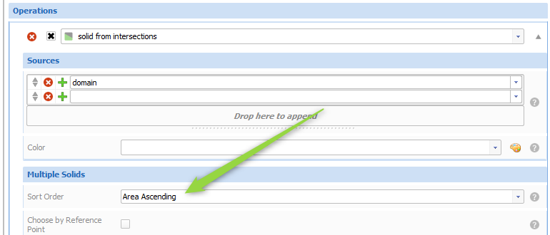
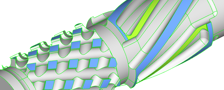
The CAESES® geometry kernel received many great improvements both in terms of robustness and performance. There are also new features available, such as selecting solids based on their surface area. It allows you to always choose the same solid after the operation “Solid from Intersection”. The former default setting was an unsorted list of generated solids where the order could potentially change in some situations during automated studies or optimizations.
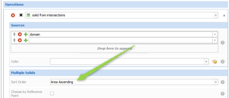
Robust during automated studies: Identify generated solids by means of their surface areas
The tolerance handling of trimming and Boolean operations has been improved. It provides you with a better default performance and robustness, so that in most situations you no longer need to care too much about global tolerances. See also the compatibility notes below.
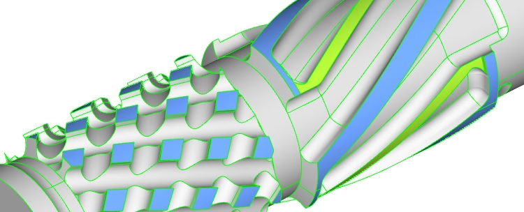
Improved robust geometry generation of complex shapes - especially for automated workflows
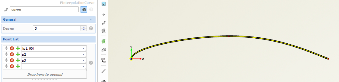
In the context of curves and surfaces, check out this new feature for the interpolation curve: In addition to a list of points to be interpolated, you can also now set tangent information for the interpolation curve. For each input point, optionally use the squared brackets for creating a list, and then add the angle in degrees right next to the point or vector. Here is an example: use “[p1,90]” for an angle of 90 degrees at the point p1 — which is shown in the following picture:
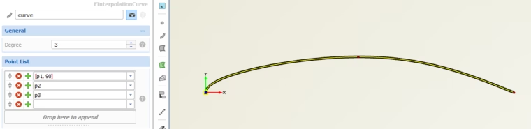
Use the squared brackets to provide more interpolation constraints such as an angle
Parasolid Export
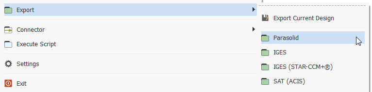
We are now offering a new add-on that allows you to export geometry by using the SIEMENS Parasolid format. If you are interested in it, please get in touch with us.
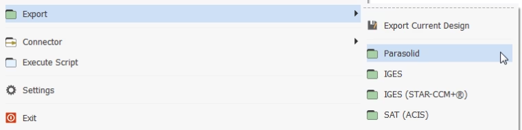
Now available: Parasolid export option
Show Results Only On Demand
So far, design results have been automatically loaded into CAESES® as soon as you click on a design in the tree or the result table. However, in situations where your result data are huge (which is often the standard situation of our customers), you potentially wait for several minutes until the data is loaded into the user interface. This can be annoying if you e.g. accidentally click on the design, or if you only want to check the design’s variables and constraints setup.
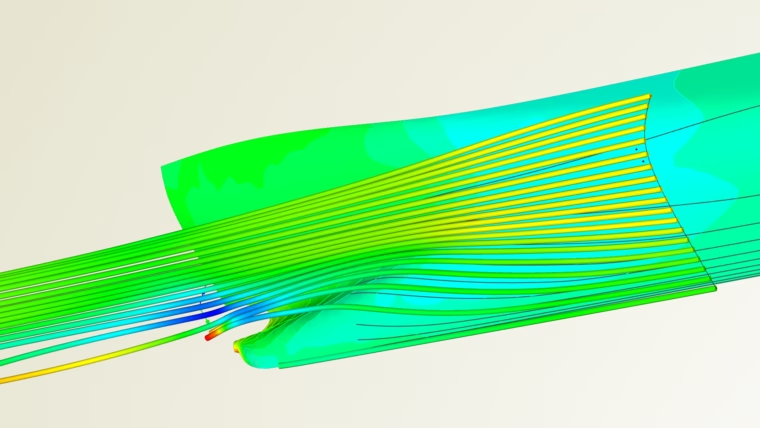
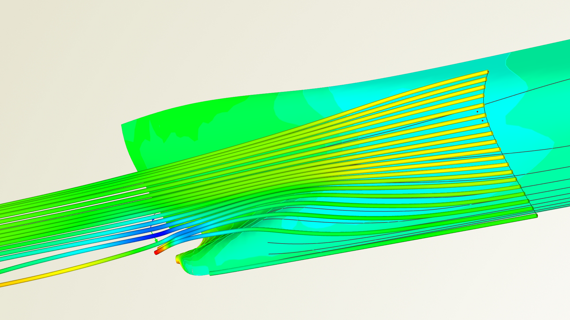
CAESES includes postprocessing capabilities
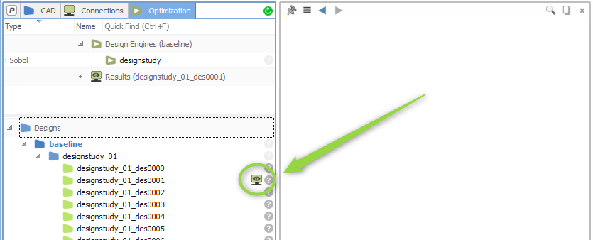
In the new version, we decided to modify this behavior. As a new default, results are now loaded into CAESES® only on demand, which is a substantial change. There is a new icon next to the design name to click on, which triggers the data loading.
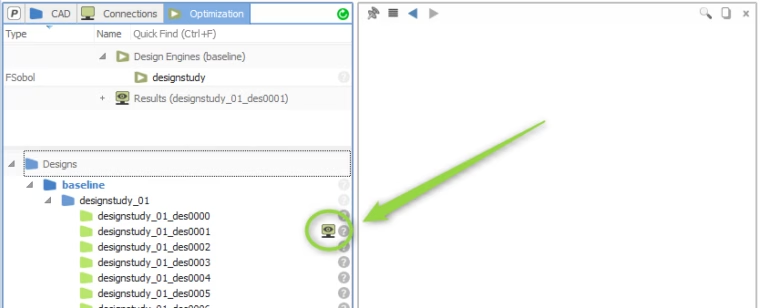
Results are now loaded on demand by clicking on this icon
At the top of the GUI, there is also an additional button for auto-loading of result data. It gives you the former behavior again, e.g. to still conveniently browse through design results in the tree using only the arrow-keys. In this context, we have also added the Results node to the optimization tab below the design engines, to give you quick access to this data when analyzing generated design candidates and their results. As a consequence, the design tree has been moved into a separate split window.
Multi-Objective Optimization: Result Pool
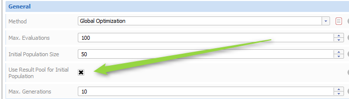
The global optimization method of the Dakota add-on which internally is a MOGA (multi-objective genetic algorithm) supports the re-use of existing designs. Previous runs can be optionally included to generate the initial population of the genetic algorithm. This avoids expensive recalculations of designs, if there are already existing suitable designs in your project. If you deactivate this result pool option, the former behavior is given, where a random number generator creates the design set for the initial population. Similar to the MOGA, the NSGA‑2 is now also able to use the result pool for all generations. In previous versions, only the first generation could be recycled.
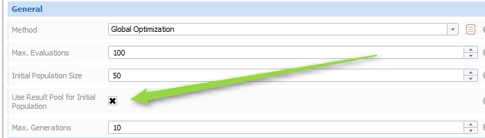
Use the result pool for the initial population of the MOGA
Design Results Table: Fixed Column
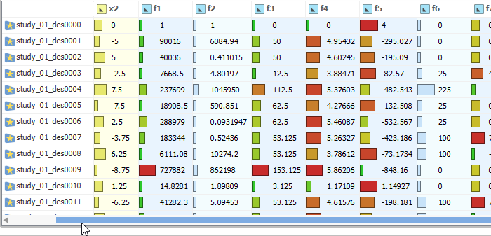
The first column (design name) is now fixed so that you can scroll in the horizontal direction without loosing the corresponding names of the designs. Objective values receive a slightly darker background in the table to better distinguish them from simple evaluations.
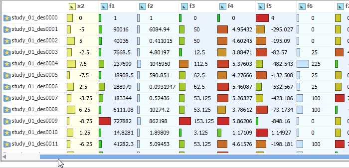
The first column is now fixed when users scroll horizontally
New Demo Model: Impeller
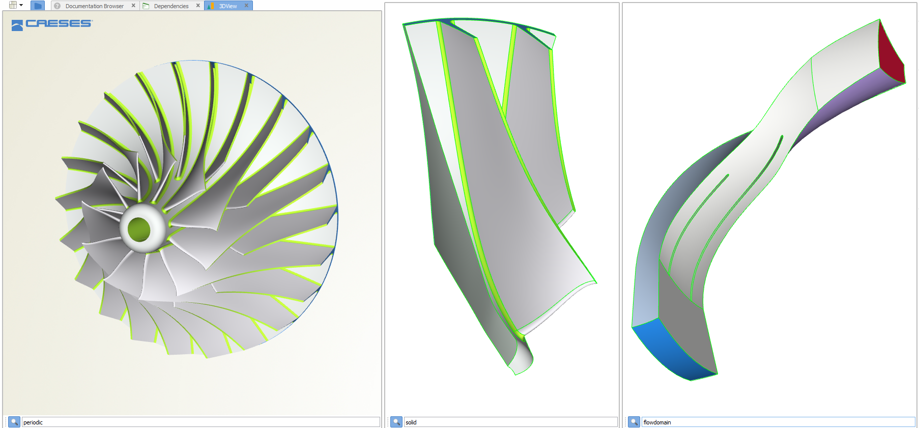
We ship a new parametric geometry model of an impeller which can be used as a reference for custom designs. The model is prepared for automated studies with simulation tools. It contains the periodic segments of the flow domain (for CFD analysis) and of the solid domain (for structural analysis).
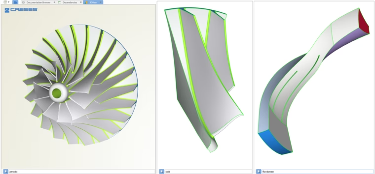
Parametric impeller for automated studies, including periodic flow and solid domain
ANSYS ACT Extension and optiSLang Add-On
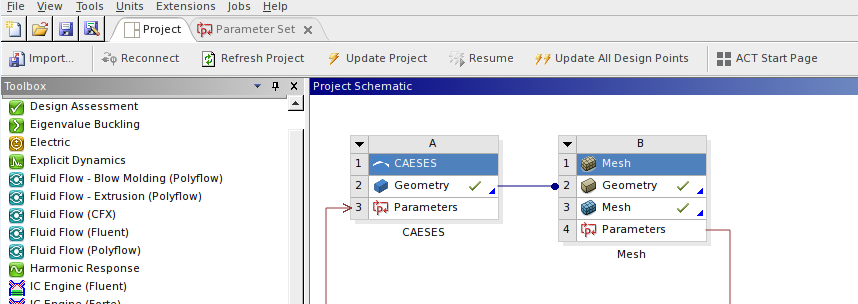
With this new CAESES® version, we are releasing solutions to seamlessly integrate CAESES® with the ANSYS Workbench and optiSLang. We have moved our CAESES®-ANSYS app from the beta phase into a productive phase: The fsc-script from CAESES® now contains additional information that allows ANSYS users to easily connect CAESES® to the ANSYS Workbench, and to automate geometry generation through the GUI of the ANSYS Workbench. There is a new tutorial available that explains how this integration works. More information about this CAESES®-ANSYS app can be found in this short blog post.
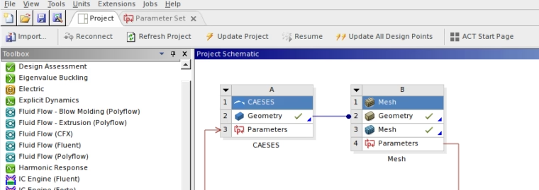
Add CAESES to your ANSYS setup via drag & drop to automate geometry generation
The new CAESES®-optiSLang add-on is now also available, to plug CAESES® into optiSLang. It provides fast access to the CAESES® model parameters (i.e., the design variables) directly within the optiSLang GUI with just a few clicks, to control the automated geometry generation.


Important Notes on Version Compatibility
We strive try to maintain the compatibility between different CAESES® versions as much as possible. This time the update has larger enhancements that fix certain bugs in order to substantially enhance the quality for generated curves and surfaces. For some very specific existing CAESES® setups, these new enhancements can lead to slight changes in geometry models. The relevant issues are:
- BREP FACE/EDGE ID: The way of generating face IDs for BReps has been further developed. One serious issue was fixed to make sure the IDs do not change during certain model changes e.g. in automated studies. If you have built up your geometry model based on face or edge IDs (e.g. by using commands such as brep.getFace(12), brep.getEdge(12)), there will possibly be a slight change of the ID ordering in this new version.
- BREP TOLERANCES: The internal handling of geometrical tolerances (BRep attribute “Global Tolerance”) has been improved to provide a better default value (i.e., if no value is set by the user), especially for challenging operations. If you have been using this setting, we recommend to remove any tolerance value in case your existing models do not work properly with this new version.
- OFFSET CURVE: This important curve type is used e.g. for profile and blade design, and we have improved the way of creating these offset curves. Input thickness distributions — that are often provided as polycurves — are now internally checked for their continuities, to automatically detect blend point positions and other relevant split locations. As a result, this leads to better 3D surfaces, but the parameterization of curves created with earlier CAESES® versions can be different now. Additionally, former problems in the leading edge region of 2D profiles for single-side creation could also be resolved due to this new implementation.
If you observe any problems in your existing projects or if you have questions about it, please do not hesitate to get in touch with us through our helpdesk.
Changes Log and Download
All details about new features, changes and bug fixes can be found in our changes log. We recommend updating to this latest version. In order to download the new installation package, please follow the link below: