Quick Guide: Geometry Scripting
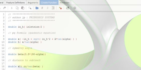
Geometry scripting is really a cool thing! It allows you to create highly customized geometry parts — parts that are often impossible to create with the typical capabilities of a graphical user interface (GUI). Most of the CAD tools on the market offer at least some basic possibilities to write small programs or scripts which allow you to regenerate geometry automatically or to run repetitive tasks with a single-click macro. Usually, these scripts can be recorded, or they are manually created by the user within some sort of proprietary programming environment. Some examples for tools with these scripting capabilities are SpaceClaim, FreeCAD or the online CAD platform Onshape with its FeatureScript.
Scripting and automation of geometry generation is THE core component of CAESES®
With our CAD and optimization platform CAESES®, this automation philosophy is really how things started off 10 years ago. This platform is nowadays a completely command-based and object-oriented structure, dedicated to getting scripted and to automate geometry-related tasks. On top of this object-oriented structure, we put an intuitive GUI which is what the user sees in the first place and how they typically start.
However, the fun part and the real magic comes up as soon as you dig into the underlying command concept. This quick guide gives you an overview of this concept and the programming capabilities that are inside of CAESES®.
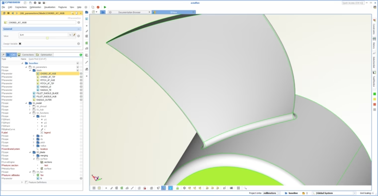
CAD model in the interactive graphical user interface of CAESES - commands are not visible in the first place
Object Types and Commands
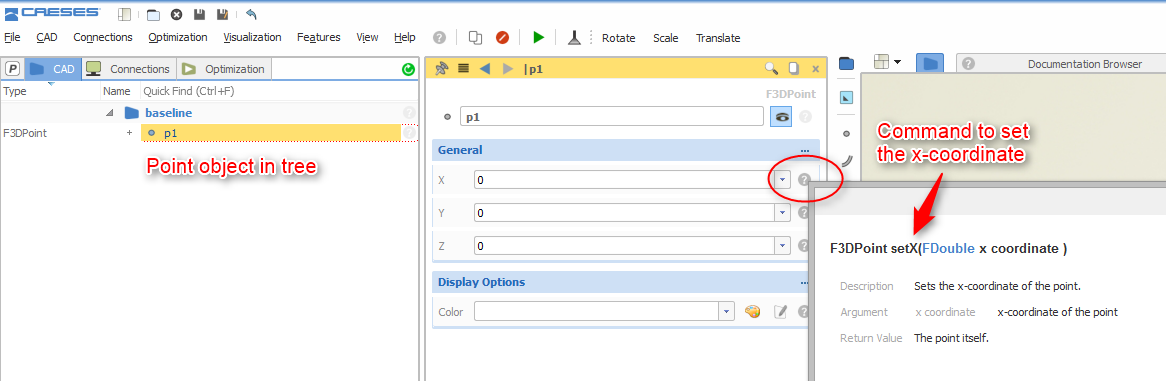
So let’s take a quick look at the foundation of CAESES®: Basically everything is an object with a certain type. For instance, if you create a 3D point with a name “p1” it appears in the object tree and its type is F3DPoint (all types start with an “F”). As soon as you select the point, you can set the x‑, y- and z‑coordinates.
Ok, this is not a big deal. However, if you click on the help icon next to the editor field, you can see which command is actually triggered in the background. In our case, it is the type command “setX()” of the point. In other words, as soon as you enter a value for x‑property, the command “p1.setX(0.5)” is executed.
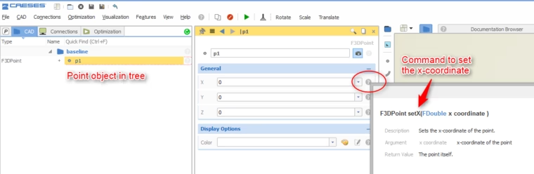
Setting the x-coordinate of a point: Show the command that is triggered in the background
Reference Manual
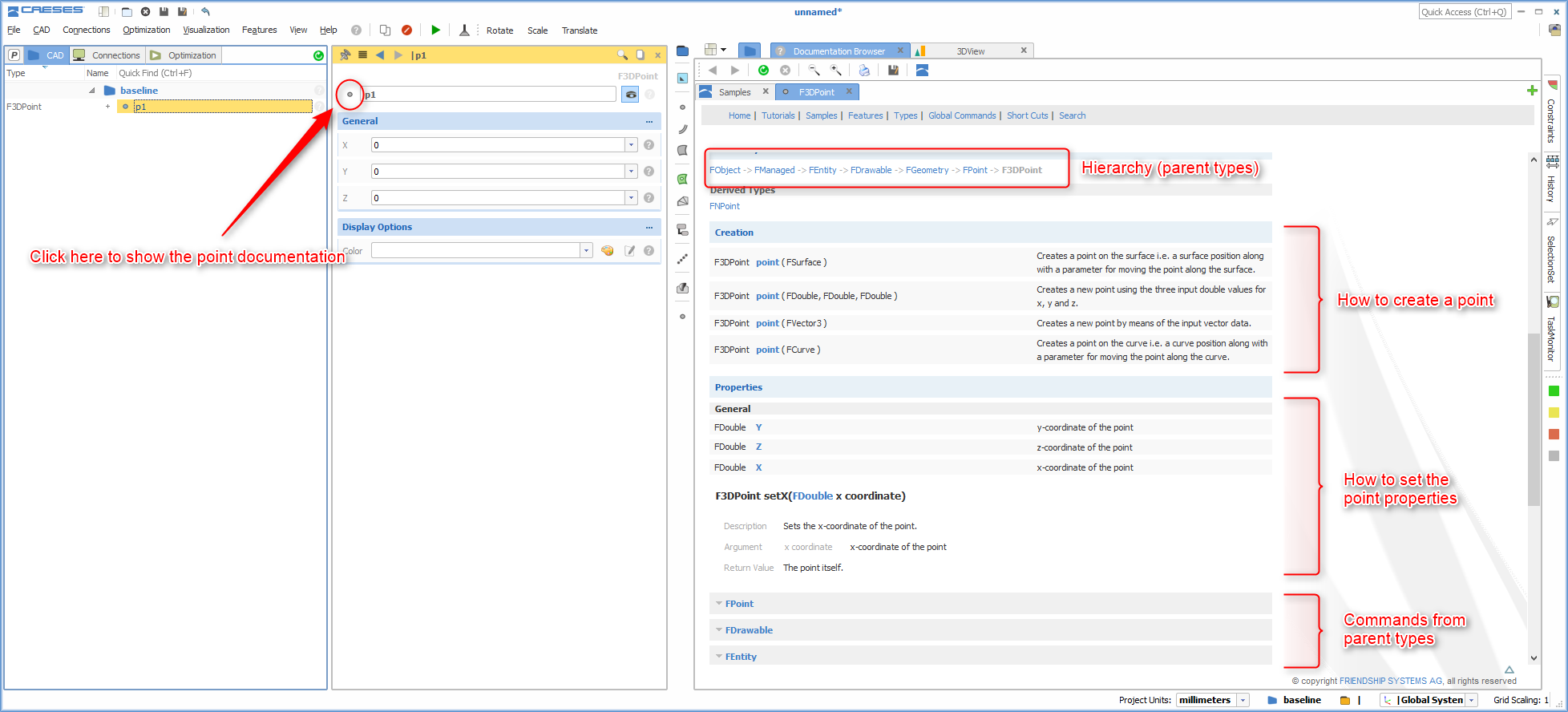
There is also documentation for each geometry type available to check the commands and the type hierarchy. Just click on the type icon in the object editor so that the documentation appears in the main window. It gives you the creation commands, the property commands such as the setX()-command and more functions.
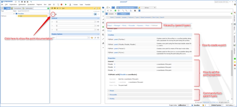
Find the type documentation to see all the available commands
Hierarchy
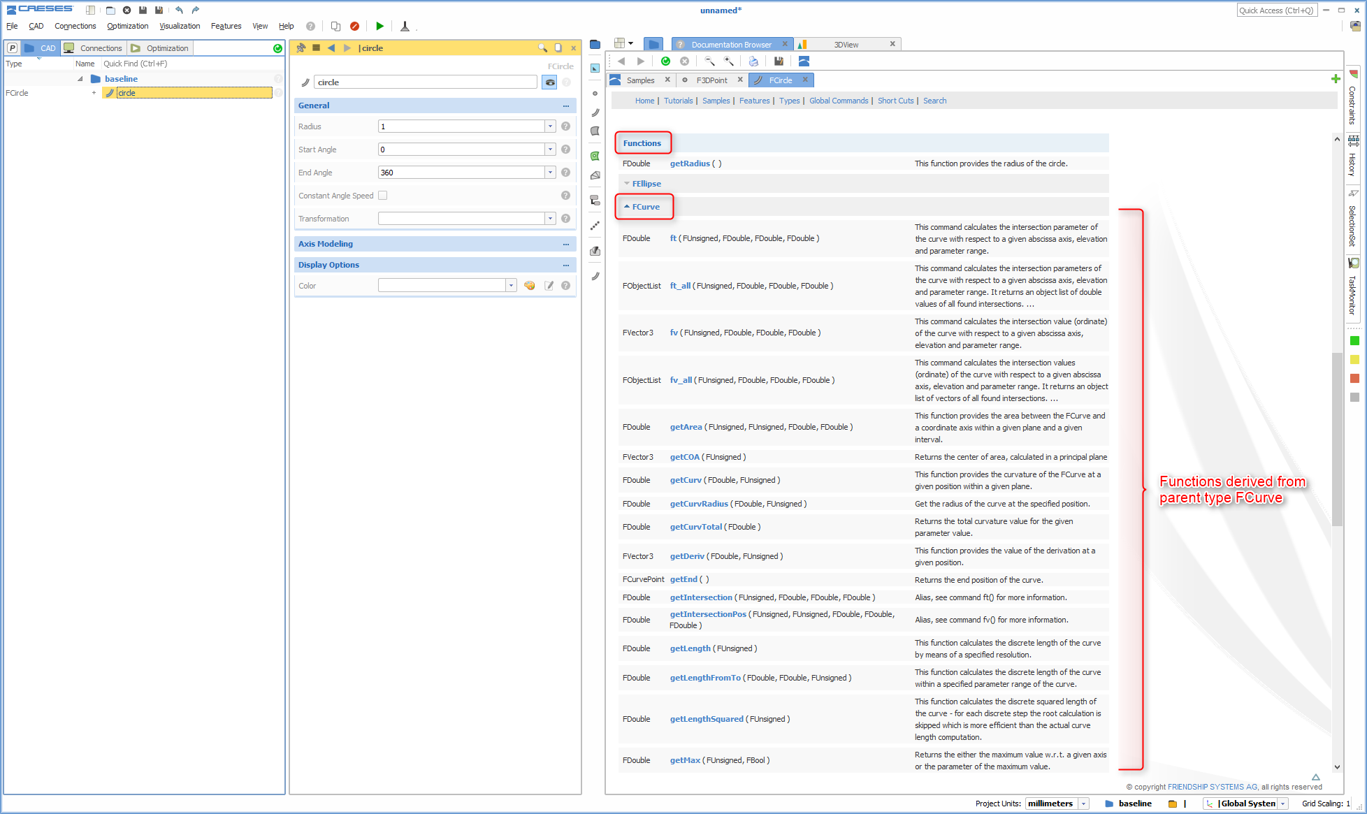
Hang on, did you say hierarchy? As already mentioned, CAESES® is an object-oriented platform — similar to what you can find the world of programming where you implement classes. Child types can derive properties and methods from parent types. As an example, the circle (FCircle) is a special type of a curve (FCurve). Other curve types are e.g. bspline curves or interpolation curves. All these specialized curves can use methods that are derived from the parent curve type.
Here are some examples: You can calculate the length of any curve using a “getLength()” command, calculate the curvature, grab a position on the curve, or ask for the start and end location. All these commands come from the parent type FCurve and they are available for all derived curve types. On the other hand, only the circle has the command “getRadius()”.
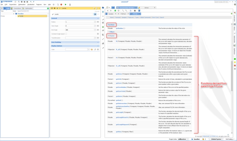
List of curve commands for the circle that are derived from the parent class FCurve
Using Commands in the GUI
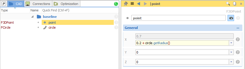
So far we know where to find the commands. How can we use them? Before we jump to the geometry scripting, let’s take a look at the GUI first. You can directly define so-called expressions in any editor where you can make use of these type commands:
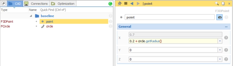
Simple example for an expression: Use the circle radius as input for the selected point
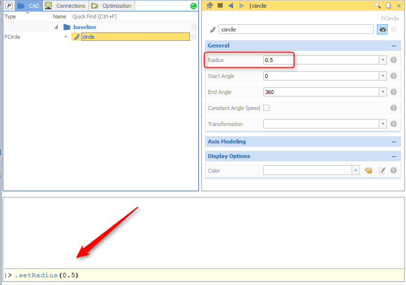
Commands can also be triggered through the CAESES® console widget if you want to try it out. Simply select the object, start the command with a dot and type e.g. “.setRadius(0.5)” to change the radius of the selected circle object. Alternatively, if nothing is selected, use the full name plus the command, e.g. “circle.setRadius(0.5)”. That’s exactly what you do when writing a script for the batch mode of CAESES®, i.e. the non-GUI mode. We will talk about it in a minute.
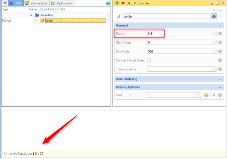
Instead of the GUI, you can use the console to set the properties such as the radius
The Feature Definition Editor
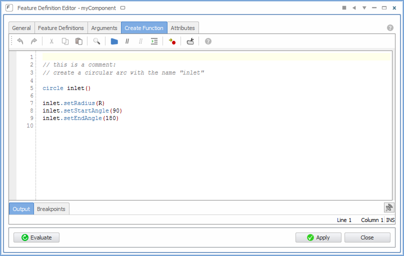
Ok, after this short introduction, let’s move forward to automation and geometry scripting: CAESES® provides a scripting environment that gives you auto-completion, comprehensive debugging possibilities and pre-defined code-snippets. An editor helps you to define your customized features using the entire command set of the platform. See the following screenshot for an example of a feature definition where a simple circular arc with the name “inlet” is created.
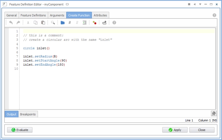
CAESES scripting editor: Create a circular arc called "inlet" with the radius R as user input
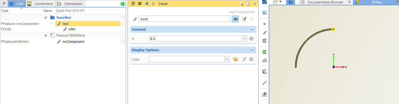
The variable “R” has been defined beforehand in the “Arguments” tab of this editor, it will be user input. The result of this code snippet is given in the next screenshot where an instance of this feature definition is shown in the tree:
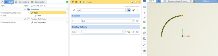
The result: A scripted circular arc
The object “test” is an instance of the feature definition “myComponent”, and the only input is the radius “R”. This feature definition is now visible in the tree, right below the node “Feature Definitions” and can be exported e.g. for re-use. It also can be modified at any time and all existing instances will be automatically updated to receive the changes.
The following video is taken from our tutorial section and shows the creation of a simple pipe geometry. In the first part, it is created interactively in the GUI. In the second part of the video, the same geometry is scripted and wrapped into a feature:
How to Create a Feature
Control Statements
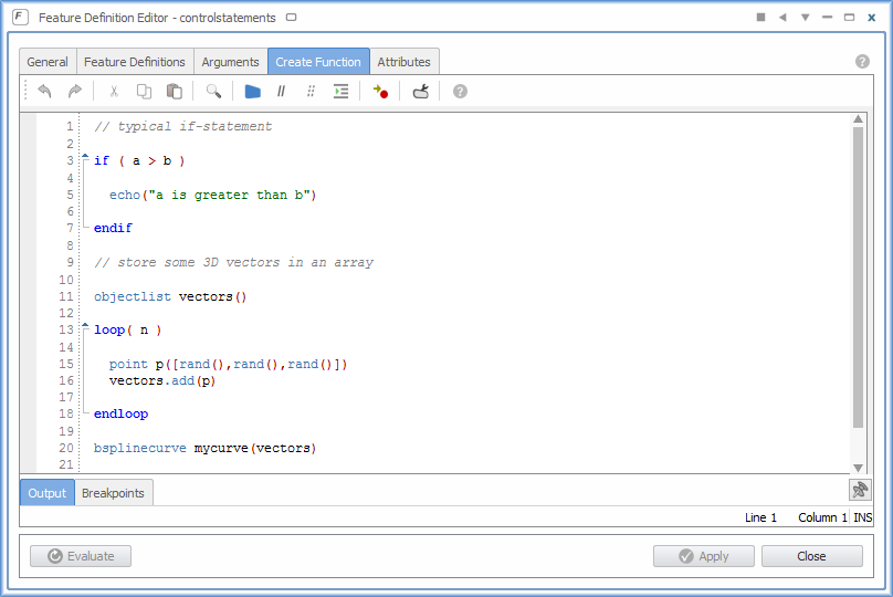
Compared to an interactive geometry setup in the object tree, you can use a variety of control statements which gives you unlimited possibilities. It results in a higher flexibility and allows you to create any kind of complex geometry. CAESES® offers the following statements:
- if/else
- while
- loop
- for each
- switch
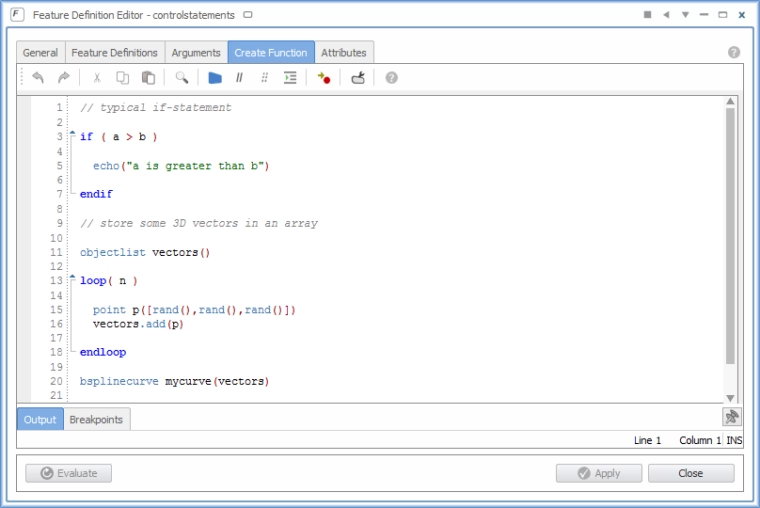
Example for geometry scripting: Control statements such as loops and if-statements
Mathematical Commands
In the documentation browser of CAESES® you will find also a set of global commands such as mathematical functions. These functions can also be used when you create your custom feature. Typical candidates are:
- sin(), cos(), tan(), atan() etc.
- ln(), log()
- crossproduct(), dotproduct()
- floor(), ceil()
- min(), max(), modulo()
- pow(), sqrt()
- rand()
I/O File Processing
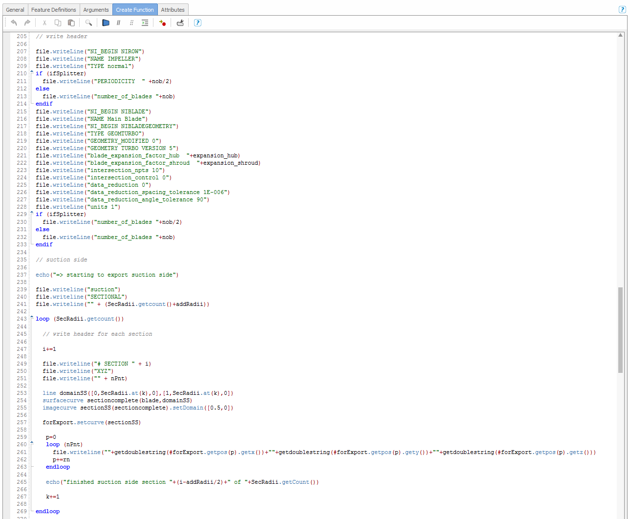
With CAESES® features, you can not only script geometry generation process, but also make use of file I/O methods to write or read files. There is a blog post “Write your own export routine” that briefly shows you how this work. This a great and simple way to implement proprietary import and export formats.
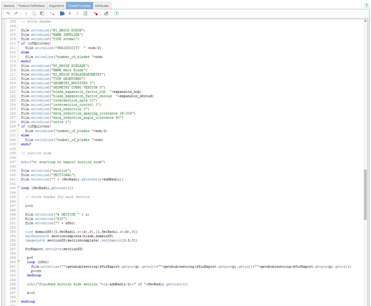
Feature definition to export geometry in a custom format into a file
External Processes
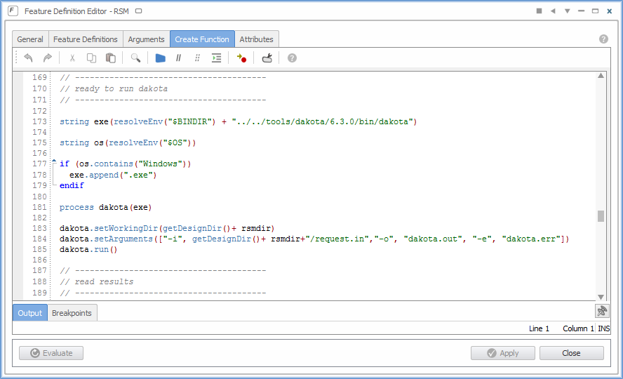
What else can you do with this scripting environment? Similar to typical programming languages, there is also the possibility to trigger external processes within such a feature. The feature waits for the process termination, and you can continue afterwards with e.g. collecting the result data. Here is an example where an external process is triggered:
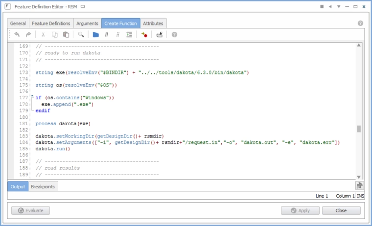
Run an external process along with defined arguments and a working directory
Don’t panic. You don’t have to understand each detail from the feature definition above — we usually do not teach this in our basic training. It’s there just to let you know that this is possible with features in CAESES® ;-)
Batch Mode
All these features often wrap complex command sequences into a single object where you as the author define the input. Such an object can be used in the GUI, as a part of an assembly or to process any kind of repetitive task.
Besides this, there is another interesting capability when it comes to scripting and automation: The batch mode of CAESES®. This mode does not start up the GUI and it is one reason why CAESES® is used in so many leading CAE companies. It allows users to plug-in a powerful geometry engine into an existing design process without any serious workflow changes. As a result, new geometry design candidates can be robustly generated with a simple script call.
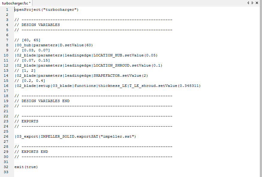
And how does it work? The design variables of a CAESES® project are also just objects whose values can be changed by using a set()-command. Check out a typical control script to run CAESES® in the batch mode:
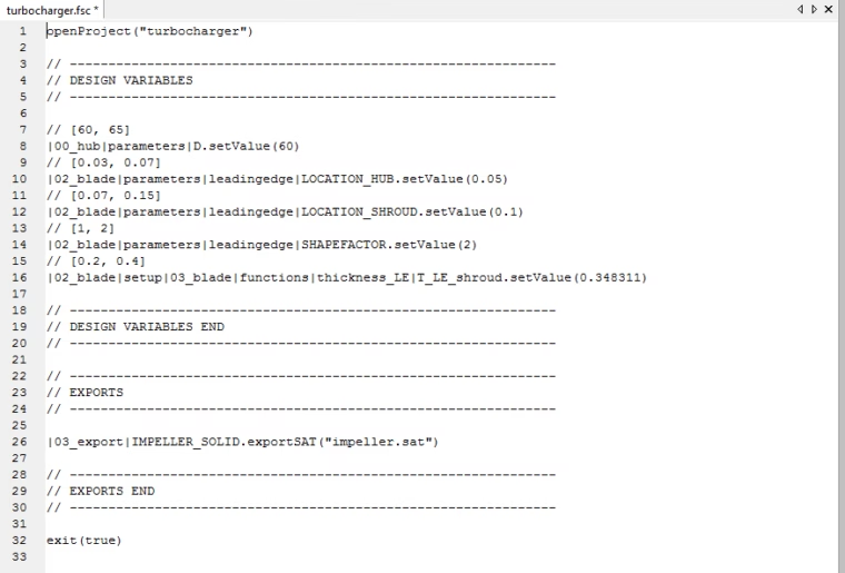
Script file to run a CAESES model in batch mode
The command to run the batch mode is simply “CAESES_crt.exe turbocharger.fsc”. This script
- opens the geometry setup (e.g. a parametric turbocharger model),
- changes the variables according to the given values (typically done by a third-part optimization tool) and
- exports the new geometry into the current project directory.
If you are interested in this, there is plenty of information about the batch mode in the CAESES user forum.
Example:
Solid Geometry Creation from an ASCII File
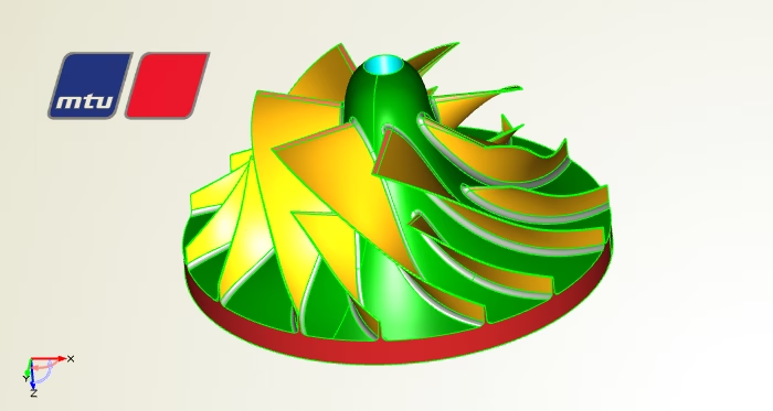
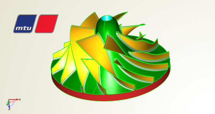
An example where geometry is generated from an ASCII file is described in the article “Automated Solid Generation for Structural Analysis at MTU Friedrichshafen”. Simple geometry data is read in using a proprietary format. From the data, a solid geometry is created automatically. The entire process is scripted and automated CAESES® using feature definitions and functions for I/O, loops, control statements and geometry creator methods (API).
More Information
Of course, this has been only an overview of the general concept and the main features. For an expert CAESES® user, these scripting capabilities are essential and really the stuff that makes CAESES® also a fun tool ;-)
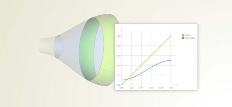
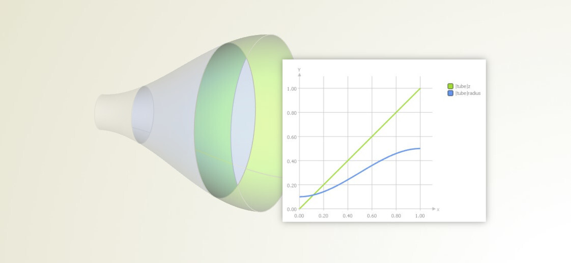
Advanced sweep surfaces based on feature definitions
You can find several tutorial videos about scripting and feature definitions in our video section. There is also a post about meta surfaces, where feature definitions play a central role for the creation of advanced sweep surfaces.
If you have more questions, don’t hesitate to drop us a line.