Propeller Design: Comparison of Blade Sections
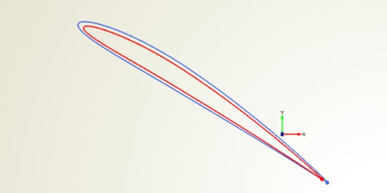
If you need to compare one propeller design with another one — e.g. a new design candidate that is derived from the baseline — it helps a lot to have the 2D section information at hand. When you set up a parametric blade model in CAESES®, you can typically access the 2D curve directly so that it is easy to compare a baseline with a new design. However, if you have the baseline design given as an imported NURBS surface or as simple point data, then you need other ways to bring back the 3D information into the 2D space.
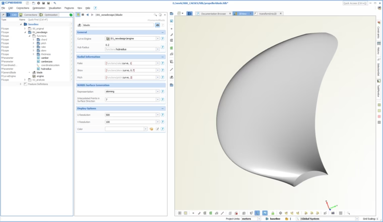
How to compare the 2D sections of a new design candidate with the baseline?
The Reverse Transformation
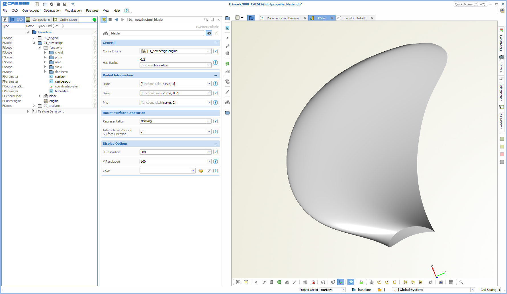
Let’s say we have an imported baseline design i.e. a blade surface, and we additionally created a new parametric model in order to optimize the blade shape. So how can we now compare the section changes at a specific radius? Here is a possible quick solution:
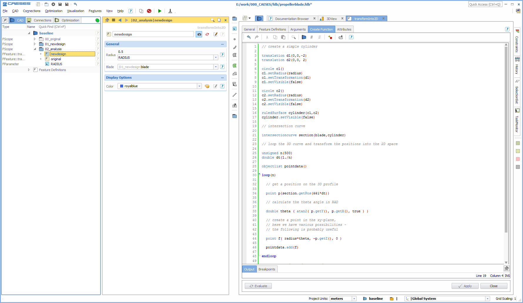
- As a first step, intersect the blade surface with a cylinder to receive an intersection curve in the 3D space.
- Calculate a set of positions on this curve by using the “getPos()” command.
- For each position, calculate the rotational angle ‘theta’ — (oh no, trigonometry …)
- Having the radius plus the angle ‘theta’, unroll the information into the xy-plane
You can put such a sequence in a small feature which should take you not more than 3 minutes (ok, I mean, it is easy once you’ve understood the maths and the idea behind it…). The following screenshot shows the procedure from above, wrapped into a CAESES® feature definition (click on the image to enlarge it):
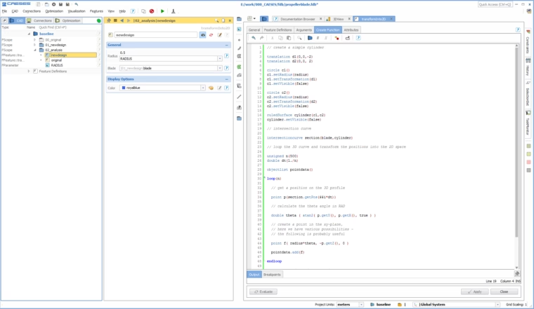
Transformation of the sectional 3D data into the 2D space
Comparison of Baseline Design and a Variant
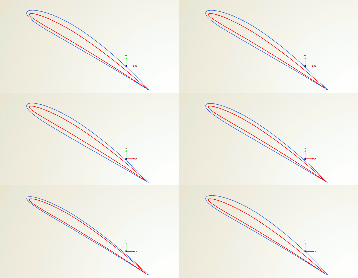
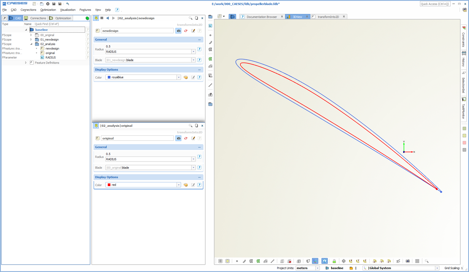
Now you create 2 instances of this feature definition, one for the baseline blade (red color) and another one for the new design (blue color). The input for these features are only the corresponding blade surface, and the radius where you want to compare the sections. Here is another screenshot that shows the 2D comparison in the xy-plane:
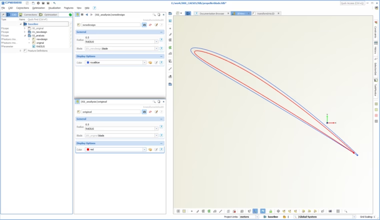
Comparison of the 2D sections
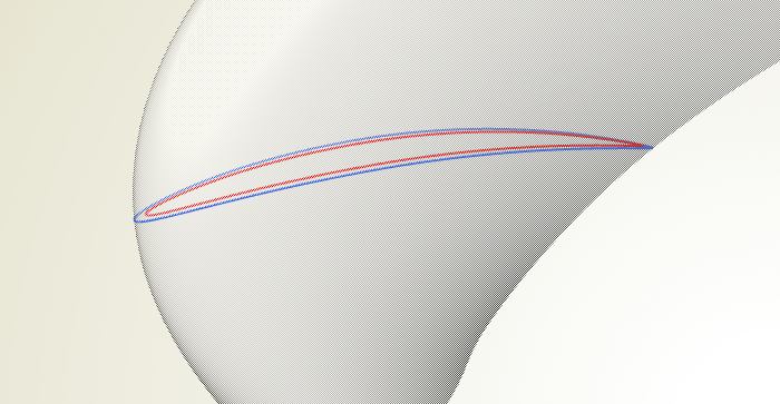
Since we have the 3D intersection available from the feature above, we can of course also compare the 3D sections, together with the transparent new blade surface:
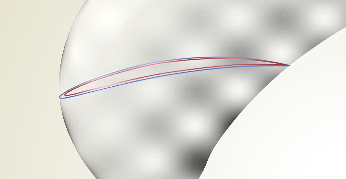
3D comparison of the two designs at a specific radius
Finally, here is an animation which shows the comparison of the baseline design with candidates that have been generated in an automated design study:
BTW: This also works for other blade applications such as fans, where you also design based on cylindrical surfaces.
More Information
Short and sweet.… You can find the project file of this post in our community forum. Let us know your thoughts about this post, and feel free to get in touch with us. Here is also another post about automatic blade generation from imported data.
If you are interested in trying out CAESES® for your application then check out our product pages for more amazing details. Note that we also offer a powerful & free edition of CAESES®, which can be downloaded from our website. There are no annoying or hidden limitations, and you can directly start to set up your own intelligent model today!