Optimal Fluid Dynamics with Ansys CFD
Ansys CFD tools like Fluent or CFX, along with the different available options for grid generation, are a popular choice for engineers when it comes to evaluating the fluid-dynamic behavior of their designs. They provide valuable insight into the performance measures of interest. But even more, automated optimization and design exploration workflows involving CFD can be realized. These significantly augment the development process by leading to better designs, shortening development times, and reducing design cycles, as well as increasing the knowledge about the product’s behavior, i.e., the influence of various parameters on its performance, early in the design process, when the freedom for making decisions is largest.
These automated processes require a suitable CAD tool that can reliably produce the different geometry variants to be analyzed. In our experience, this is a crucial bottleneck that engineers commonly encounter in setting up and running a design exploration or optimization process, with typical symptoms such as:
- Geometry variation with traditional CAD systems is often tedious or prone to failure, i.e., some or even many of the variants fail to regenerate when changing parameter values.
- It is difficult to consider, or even automatically fulfill, given constraints (e.g., due to manufacturing or packaging).
- The quality of the CAD model might not be suitable for simulation (e.g., w.r.t. watertightness or level of detail).
- Too many parameters make optimization inefficient.
- Not enough control is given over critical geometrical properties.
For the most part, our design tool CAESES® is a highly specialized CAD system that specifically tackles the aforementioned problems. It is focused on parametric modeling and variation of complex – often free-formed – geometries for the purpose of design studies and optimization. It provides efficient parameterization methods that offer a high degree of flexibility while using less parameters, superior robustness, comprehensive capabilities for integrating constraints, and simulation-ready exports that require no manual processing. Furthermore, it can be fully integrated into Ansys Workbench to be used as a dependable geometry generator for design exploration and optimization.
Ansys CFD Workflow Integration
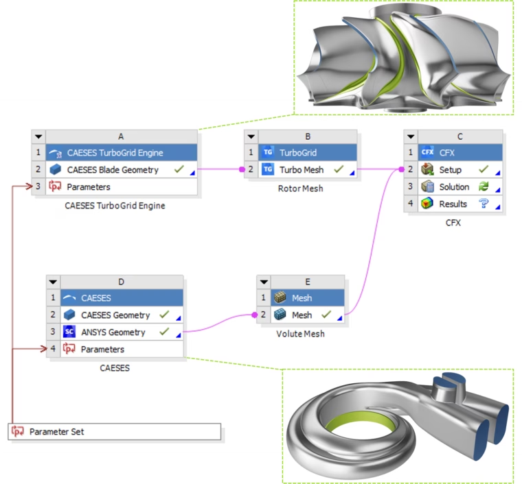
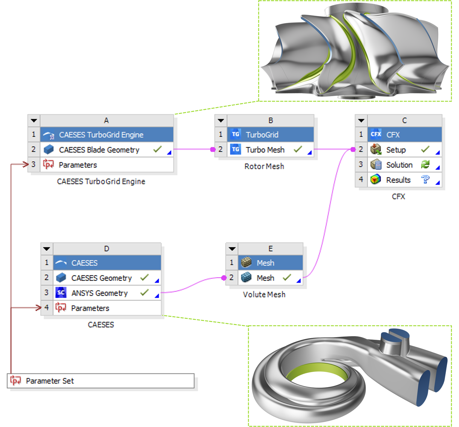
Developed with the above-mentioned concerns in mind, the CAESES® app for Ansys Workbench gives access to the full capability of the CAESES® parametric geometry modeling and variation platform. It enables you to insert any CAESES® geometry model into the user interface and the workflows of Ansys Workbench. With just a few clicks, you are ready to run large studies, such as design of experiments and formal optimizations – everything fully automated.
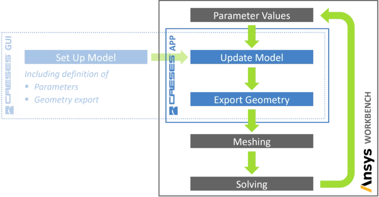
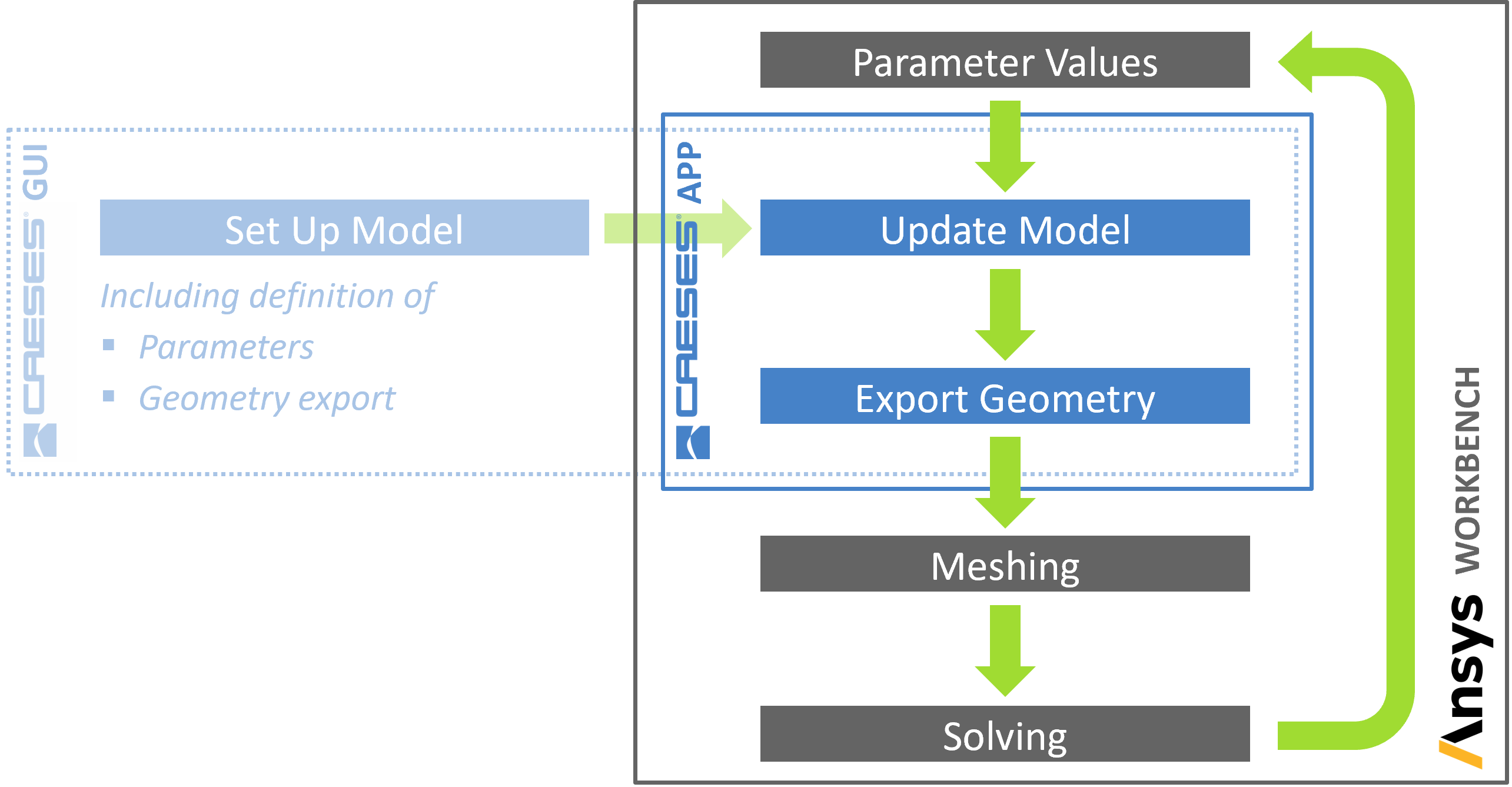
So how does the interfacing actually work? First, a parametric geometry model is created in the CAESES® user interface, including a set of design variables that control its shape. Also, the geometry export is configured: Usually, the ACIS (*.sat) format is used, which allows to transfer additional information for repeatedly identifying the different parts of the geometry. Finally, a script file is auto-generated, which controls the CAESES® batch process (i.e., opening the model, setting the parameter values and exporting the updated geometry).
A crucial component of this setup is that you are able to assign colors with user-defined names to the individual faces of the model in CAESES®, which are then transferred as identifiers to Ansys Workbench by the geometry file. This is required to automate the meshing procedure, where you need to reference the different patches of the model (by using “named selections”). The color names are later shown in the Ansys Mesher, DesignModeler, or SpaceClaim.
In Ansys Workbench, you just have to install the CAESES® app to make CAESES® available as a component. Load the script file for your current project through the CAESES® component and update it. The generated geometries are exported and loaded into Ansys Workbench automatically, where they can be connected to other workflow components.
After the update of the CAESES® component in Ansys Workbench, the design variables of the geometry are automatically shown in the parameter set. New design candidates can now be generated by changing these parameters, either manually or by optimization tools (DesignXplorer, optiSLang, etc.).
Apart from the previously described general purpose app, two more CAESES® apps for Ansys Workbench are available: the CAESES® TurboGrid app that is dedicated to bladed turbomachinery geometries and uses the proprietary TurboGrid format for the transfer of the geometry, as well as an interface app, which couples Ansys Workbench to CAESES® and allows running optimizations in the CAESES® optimization environment.
Ansys CFD Optimization Case Study: Gas Turbine Stage
A popular application for both Ansys CFX and CAESES® is turbomachinery. CFX is one of the leading CFD software solutions for turbomachinery applications and provides streamlined workflows for setup and postprocessing, as well as suitable computational models. CAESES®, on the other hand, comes with dedicated parametric modeling environment for all turbomachinery components, like axial and radial blades, casings, and volutes.
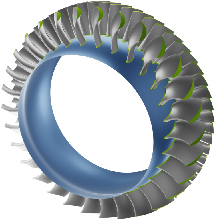
The subject of this investigation is an axial turbine stage consisting of a stator with 30 vanes and a rotor with 59 blades. Following boundary conditions are applied:
- 25,000 rpm
- 400 kPa total pressure at the inlet
- 1,000 K inlet temperature
- 262.4 kPa static pressure at the outlet
- A mass flow of approximately 6.3 kg/s at the outlet
The objectives of the optimization are to maximize the isentropic efficiency, as well as the power.
Geometry Parameterization
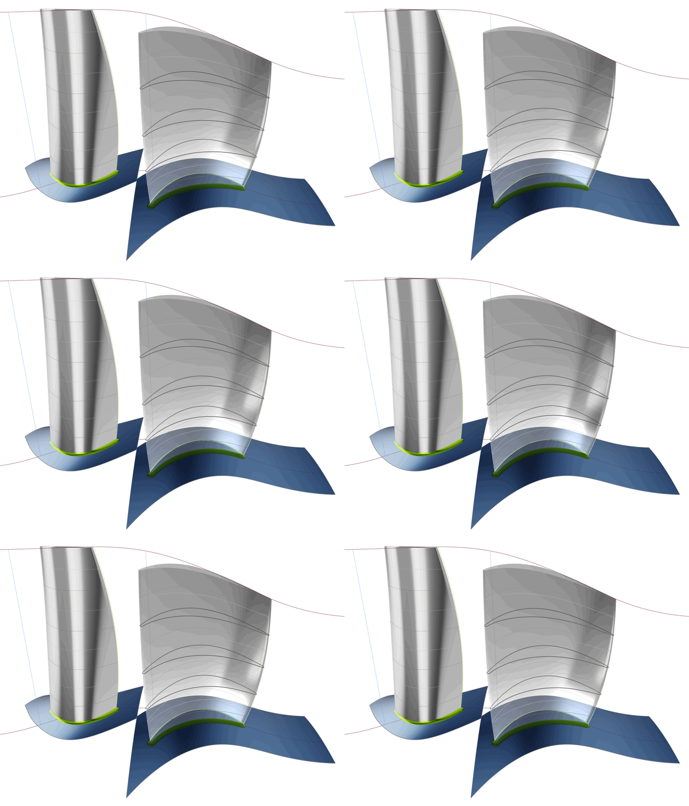
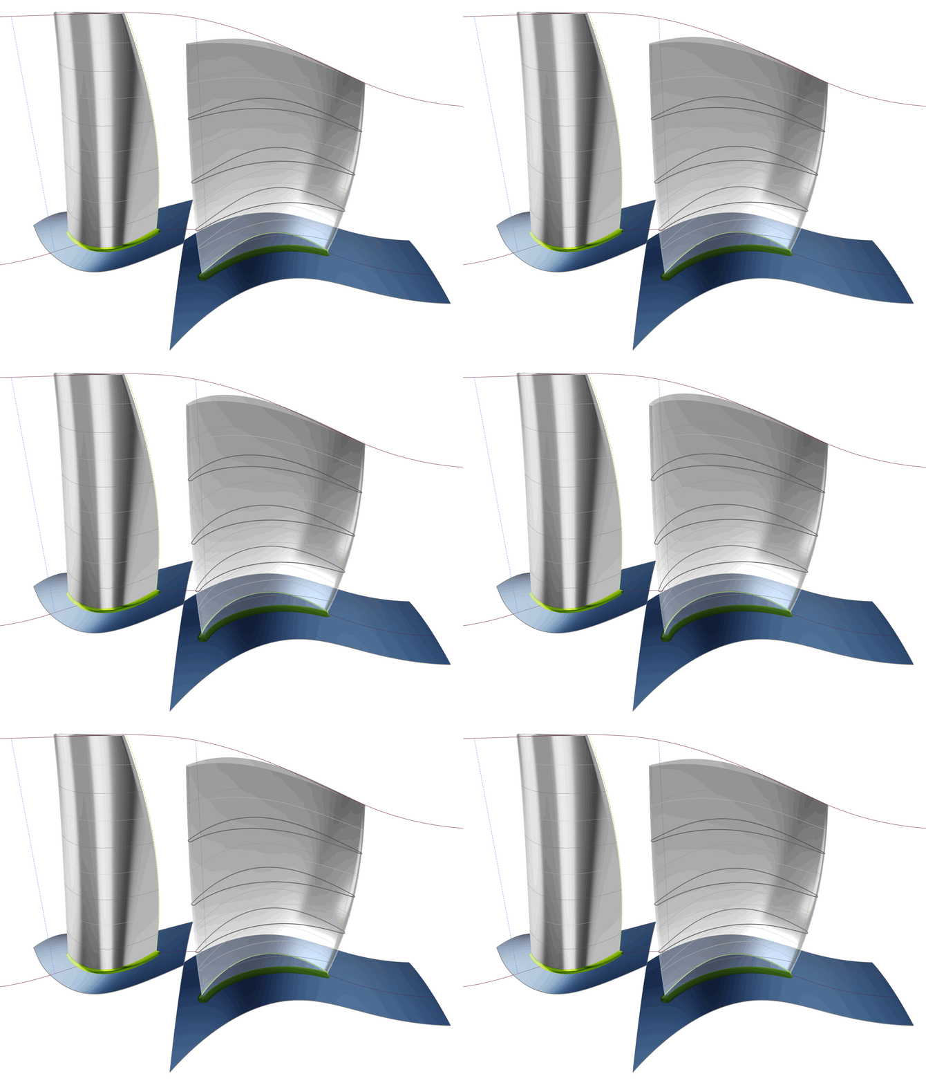
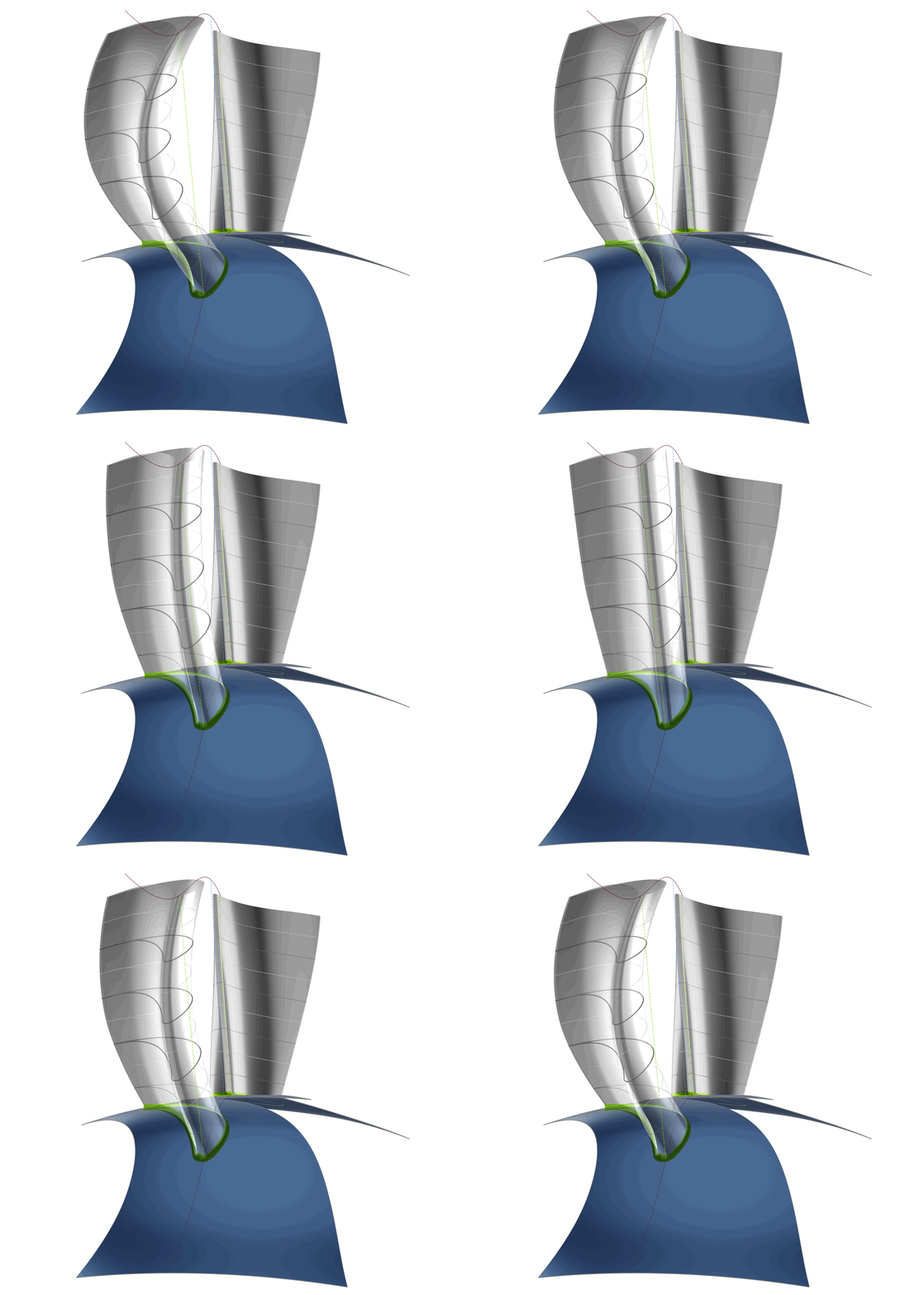
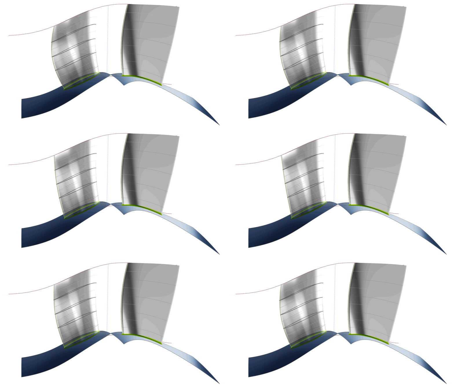
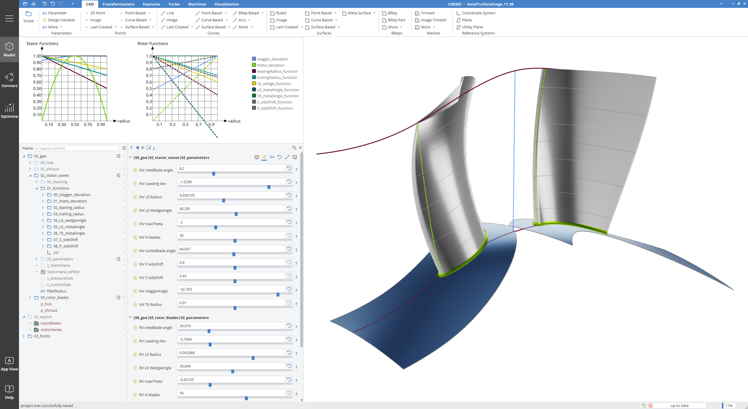
The geometry parameterization is based on a parametric 2D airfoil definition, which gets transformed to a stream surface and obtains its corresponding set of parameter values from radial distribution functions. Using this approach, the exact 3D airfoil shape can be derived for any arbitrary radial position and the blade surface can be generated as a continuous sweep. The design parameters are then applied to the shape of the radial distribution functions, as opposed to discrete airfoil sections, allowing for a flexible but efficient variation of the geometry. Additionally, the shape of the (leading edge) stacking curve can be controlled for further variability.
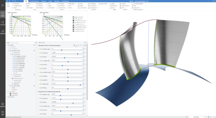
Turbine Stage in the CAESES GUI
7 design parameters are defined for rotor blade and stator vane, respectively, for a total of 14 optimization variables. These control:
- Stagger angle
- Leading edge radius
- Leading edge wedge angle
- Leading edge metal angle
- Trailing edge metal angle
- Circumferential bow (stator) or lean (rotor)
- Axial bow
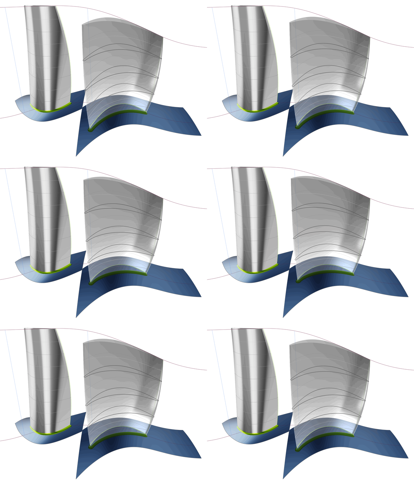
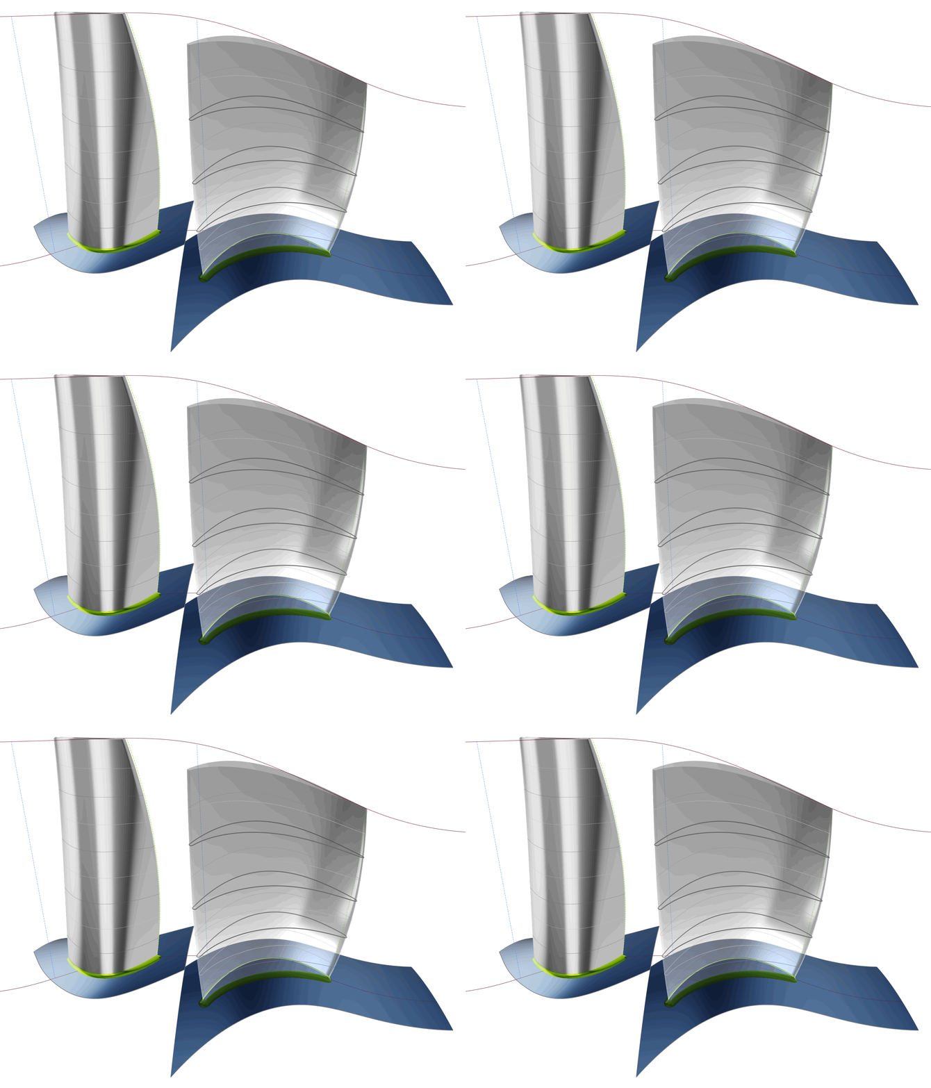
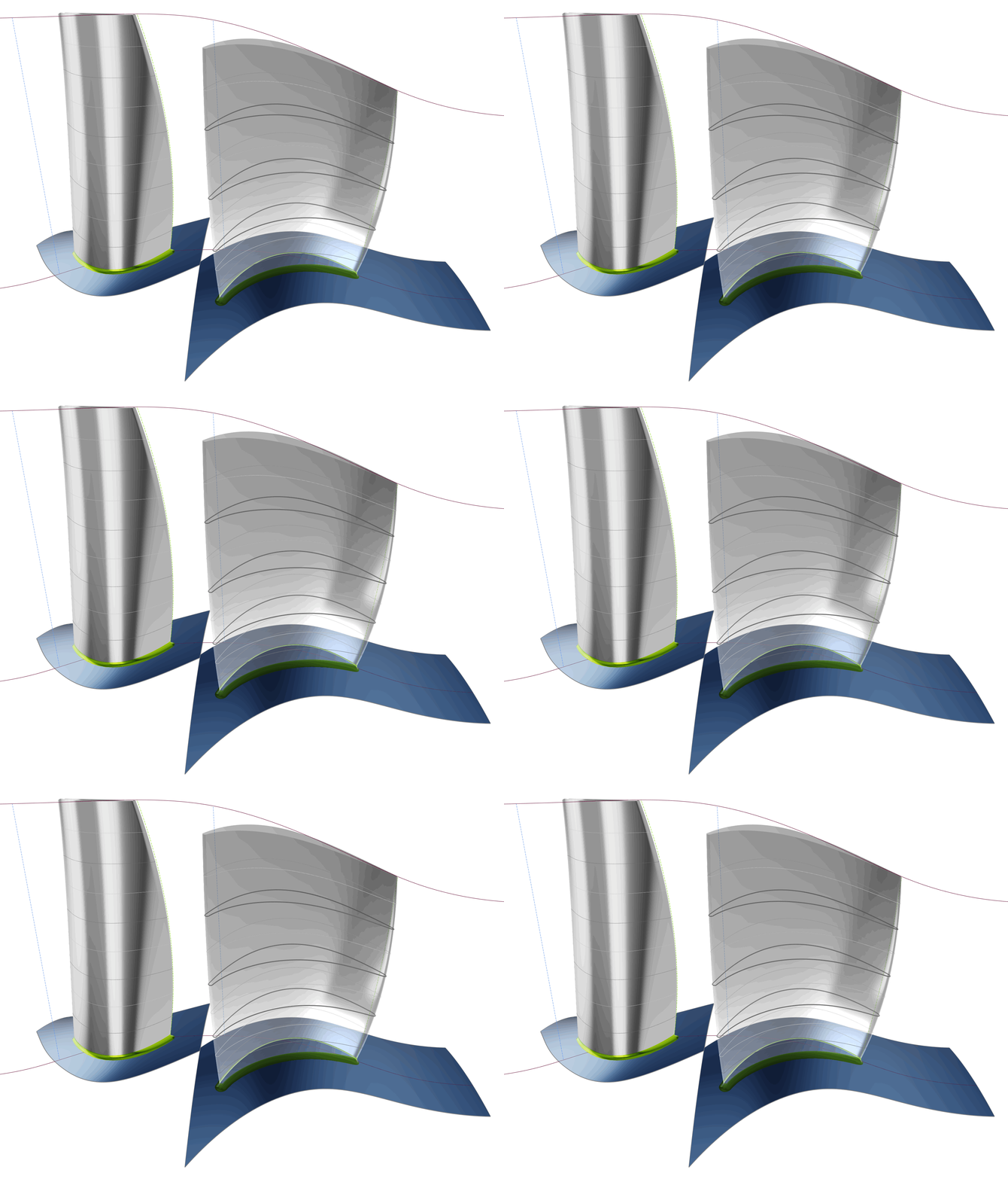
Workflow Integration
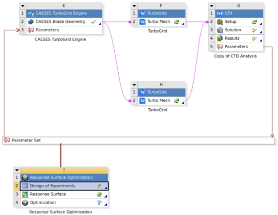
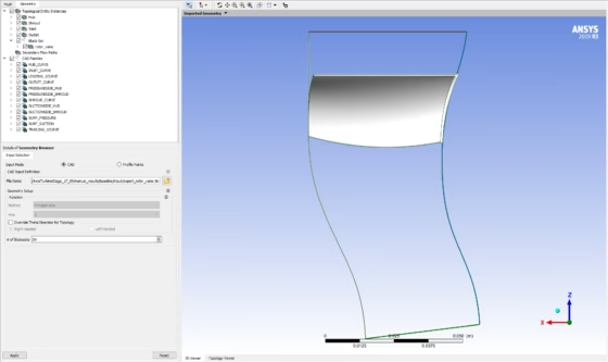
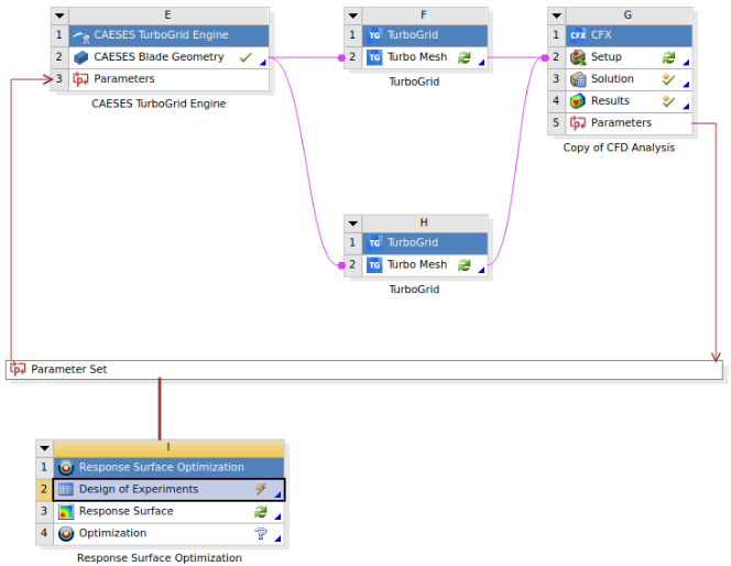
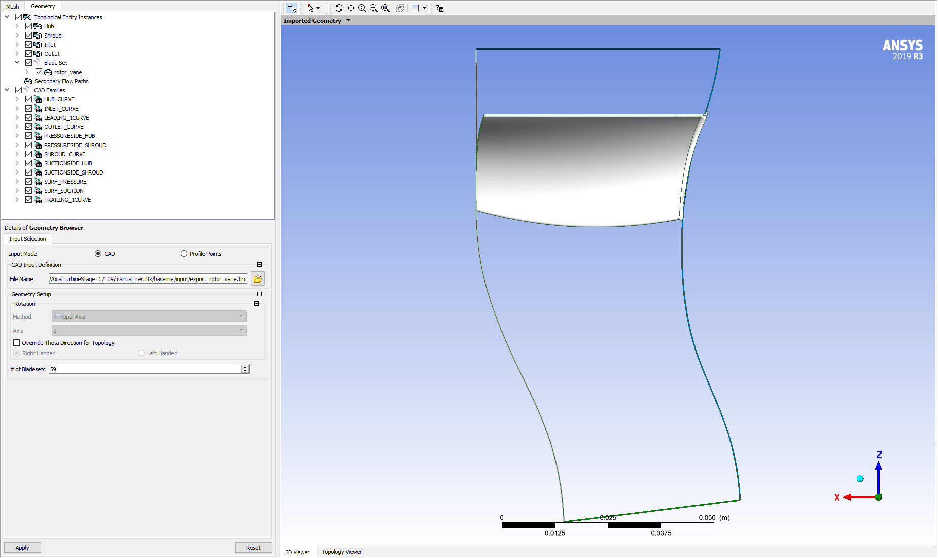
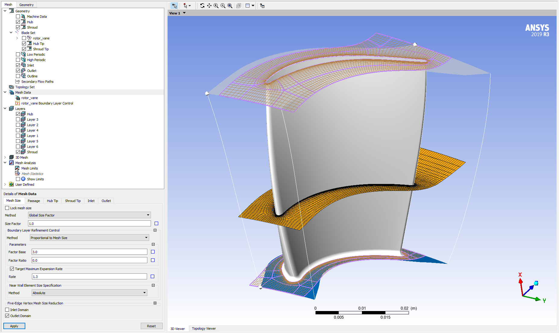
The dedicated CAESES TurboGrid app is used to integrate CAESES in the Workbench process. This uses custom exports to transfer the bladed geometry to TurboGrid as either sectional data or surface geometry. The exports take care of all necessary preparation steps to provide files that can be interpreted in the automated process by TurboGrid. Sectional data include point data for a given number of blade sections, as well as hub and shroud contour, while the surface geometry also includes boundary/feature curves and is exported in ICEM Tetin format.
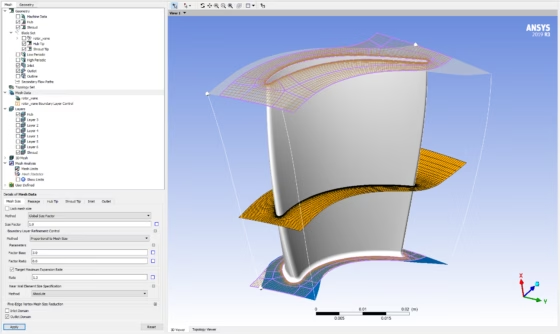
Two separate TurboGrid instances are used for stator vane and rotor blade and the combined case is solved in CFX, with a computation time of 5 – 10 minutes per variant.
Optimization Process and Results
While, strictly speaking, a formal optimization was not carried out, the investigation consisted of a thorough design space exploration with 268 design using a Latin Hypercube Sampling process through the Ansys DesignXplorer. The results formed a rather well defined “Pareto” frontier, from which improved designs could easily be identified. Furthermore, the results showed a most pronounced correlation of the objective functions with the trailing edge metal and stagger angles for both rotor and stator.
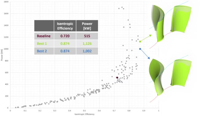

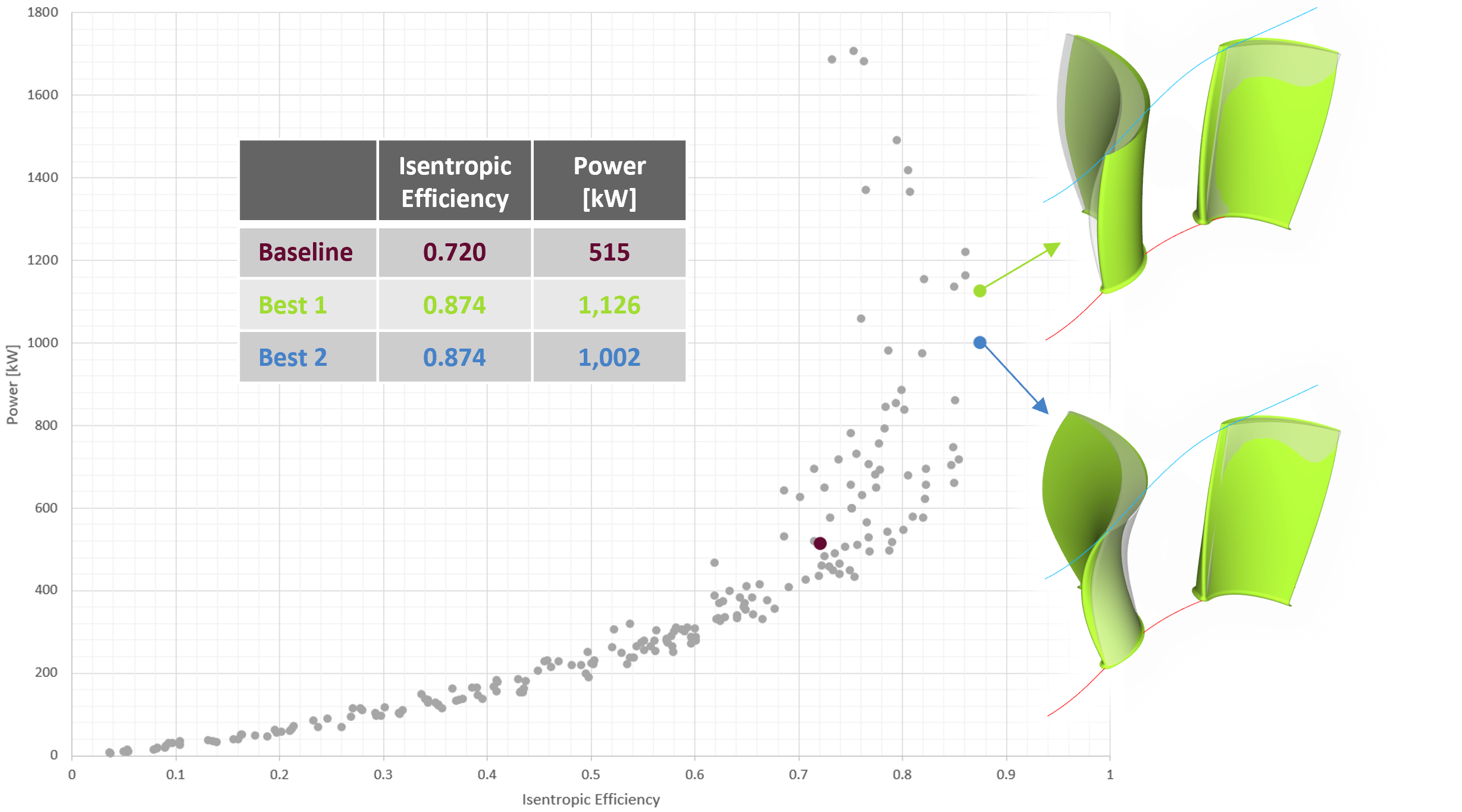
Optimization results: comparison of numerical values and geometries with baseline
This design study resulted not only in two significantly improved design candidates, but also demonstrated the efficacy of the simulation-driven design approach using Ansys CFD in combination with a powerful geometry processing, as provided by CAESES®.
More Information
Watch the webinar recording about this case study here.
See this overview for the possibilities and capabilities that CAESES® offers for turbomachinery design.
Questions?
Please do not hesitate to get in touch with us if you have questions in the context of your specific application. We look forward to discussing it together with you!