How to Define the CAD Geometry for a Turbo Inlet Duct
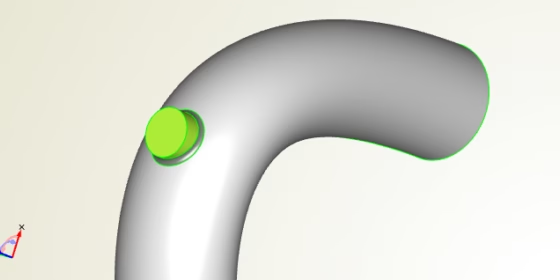
When you design high performance engines in the field of motors sports, you can find a variety of complex duct geometries, air intake manifolds and other weird-shaped components. In order to increase the horse power of the engine, you can try to find the optimal shape of these geometries. For the advanced design of e.g. high flow turbo inlet ducts, a flexible and variable CAD geometry can drastically speed up the overall process. With a set of design variables, automated optimization strategies are able to change the geometry shape such that your objectives are minimized or met (pressure losses, uniformity, targeted flow characteristics etc.). At the same time, it is important not to violate the given space constraints.
Geometry Setup for the Turbo Inlet Duct
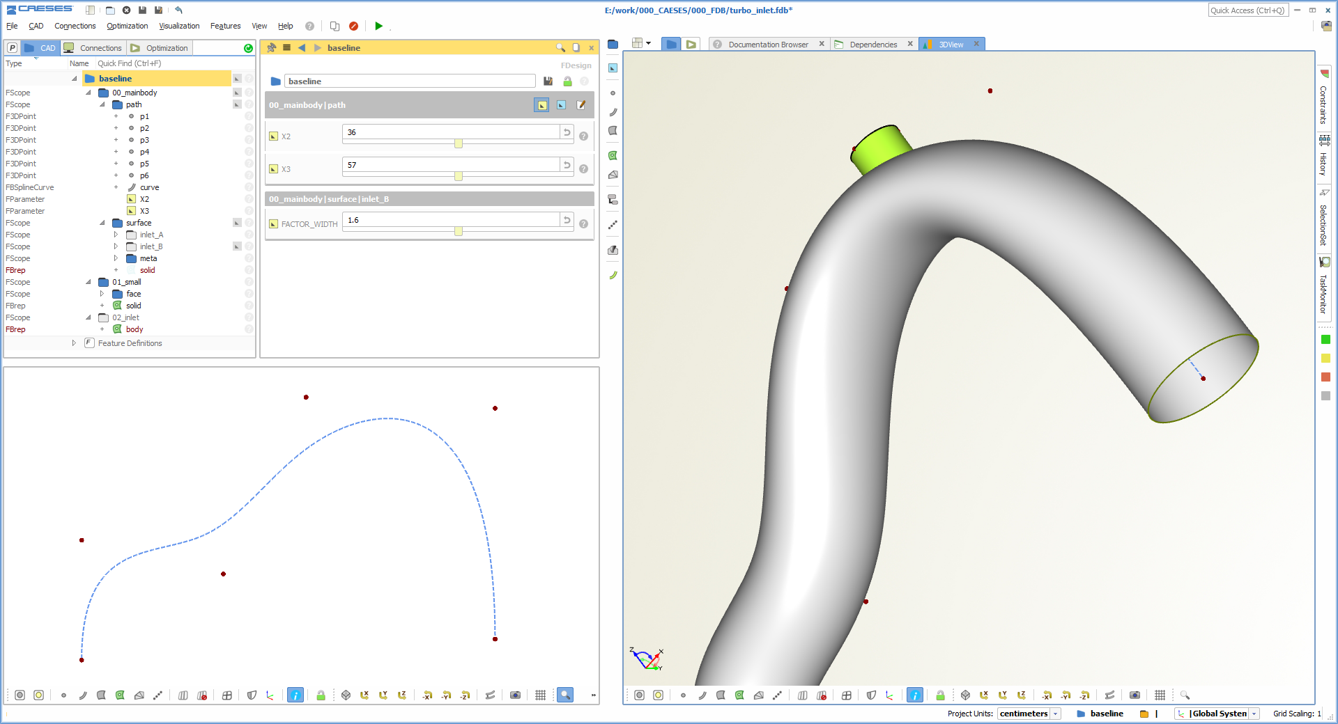
For this article, we have created a simple demo model in CAESES® that shows the basic steps to set up the variable geometry. You first start with a path curve which in our model is a simple bspline curve. The control vertices of the curve can be controlled by design variables. These variables are changed manually by the user, or they are changed fully-automated by parameter study strategies or optimization algorithms.
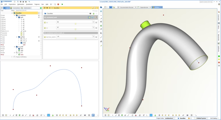
CAESES model of the turbo inlet duct
Besides a variable path curve, the shape of the duct shall also be variable while sweeping along the path: For instance, the shape changes from a circular shape to an ellipse shape at certain regions that can be defined. A function graph controls where to smoothly introduce the ellipse shape. Typically, this is a feature that helps to improve the flow in highly curved regions. Below you can find some animations that illustrate this behavior.
Variation of the Model
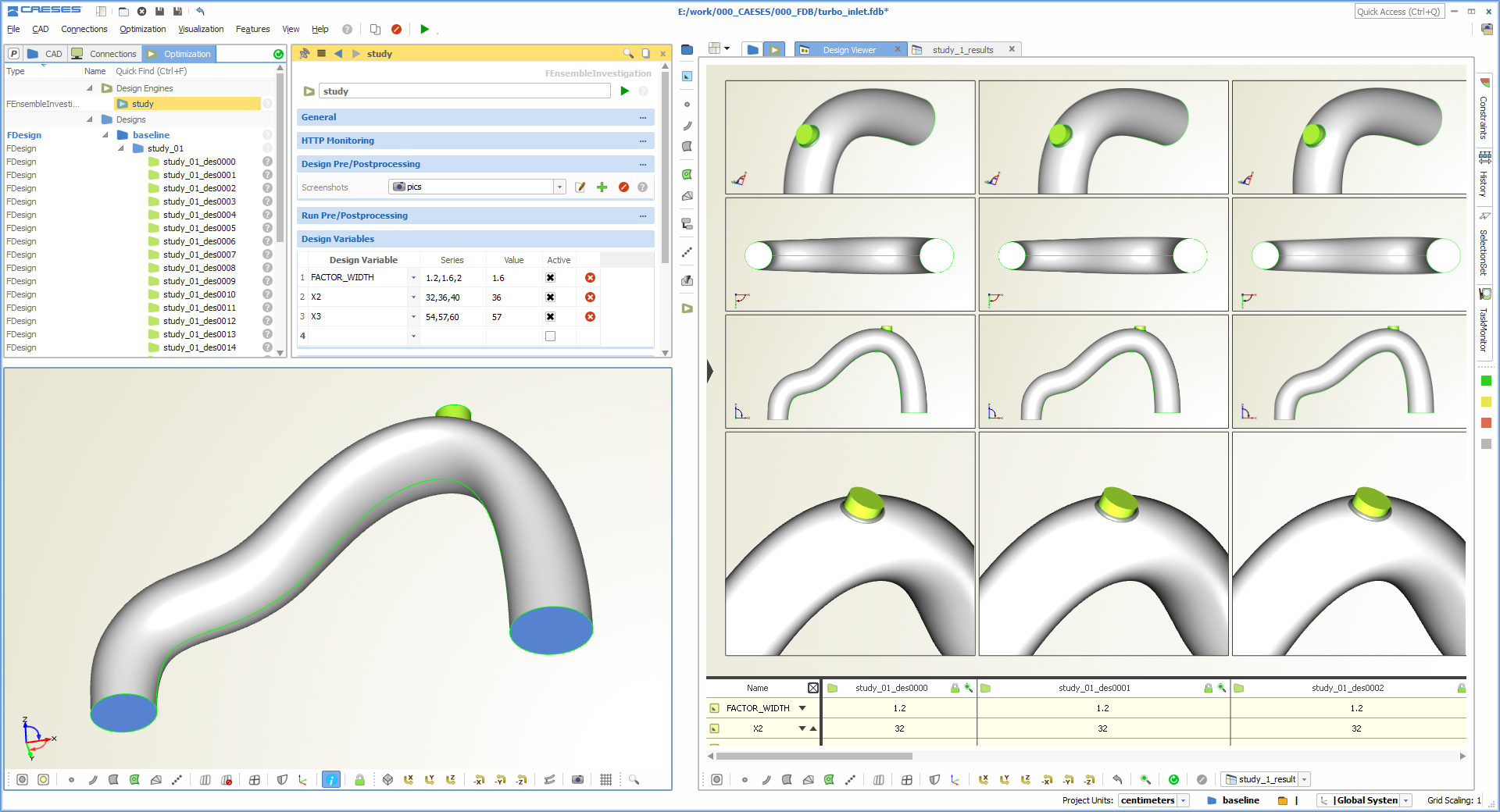
Once your geometry is ready, it can be connected to a simulation software (typically CFD), to receive the relevant flow quantities that actually shape your design. The generated variants can be assessed in the design viewer of CAESES®:
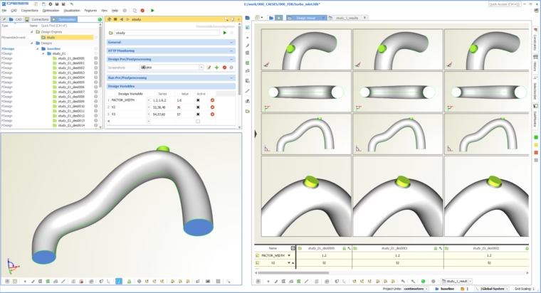
Automatically created variants of the turbo inlet duct
In order to give you a better idea of the possible changes, take a look at the following animations:
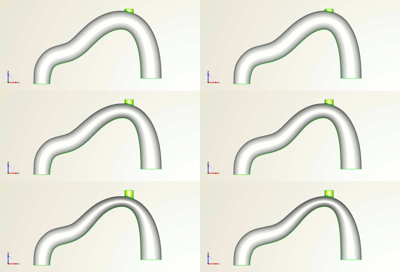
Turbo inlet duct, shown from the side
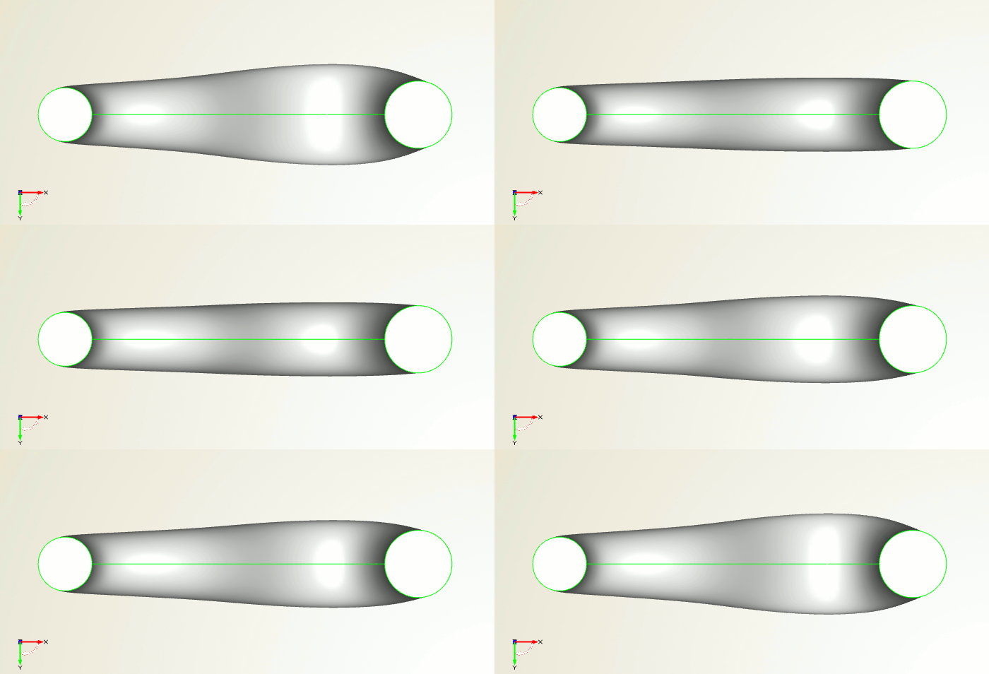
Turbo inlet duct, shown from the front
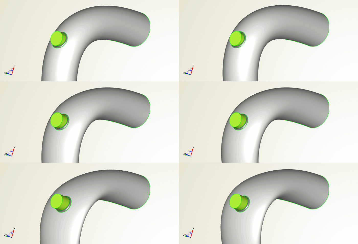
Turbo inlet duct (region where we squeeze the shape)
Video
Finally, check out this short video which gives you an idea of how it looks when playing with this model in CAESES®:
More Information
You want to learn more about CAESES® for automotive applications? Then check out the product pages for more details.