Gear Pump Design
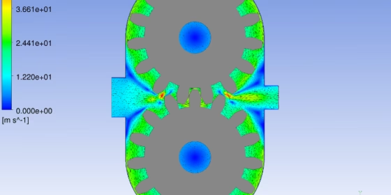
Some time ago, one of our customers visited us in Potsdam. We were talking about our joint efforts to optimize various automotive components, when he came up with the wish of optimizing their gear pump designs. Well, frankly, our expertise with gear pumps is quite limited and we were not sure whether CAESES® can do the job of designing gears. However, we had a strong gut feeling that we have everything in place for it. We just needed to create a functional geometry model, while the customer could then add his expertise in simulating these products. Since the shape is “only” a geometrical definition, including a good portion of interesting maths, we wanted to check it out.
The Parametric Model
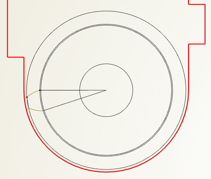
One of our engineers had spent a couple of days to find out how to create a spur gear pump. So he started off with inlet and outlet design as well as the fundamental curves of the device. There are some mathematical formula to set up the size of these circles (more detailed: the root, base and pitch curves).

Tooth along with the fundamental gear pump circles
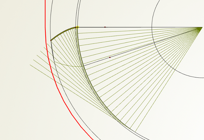
The tooth itself was constructed by means of an involute. Basically, you connect the ends of the straight lines that are tangential to one specific circle. The length of such a straight element is calculated by another mathematical expression. This is an iterative process, which can be wrapped into a feature definition of CAESES®. Feature definitions are wrapped command sequences, similar to a small program or script. You can create them interactively, or manually by typing in your sequence, including loops, if-statements and so on. In our case we needed to write to a command sequence that increments the rotational angle by a certain delta, generating the straight lines that get connected after finishing the loop. The selected curve (colored yellow in the following picture) shows the result of the involute process:
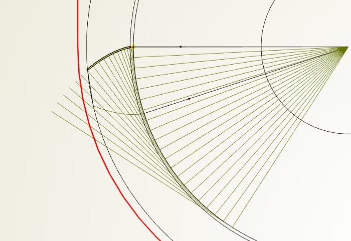
Tooth creation based on involute
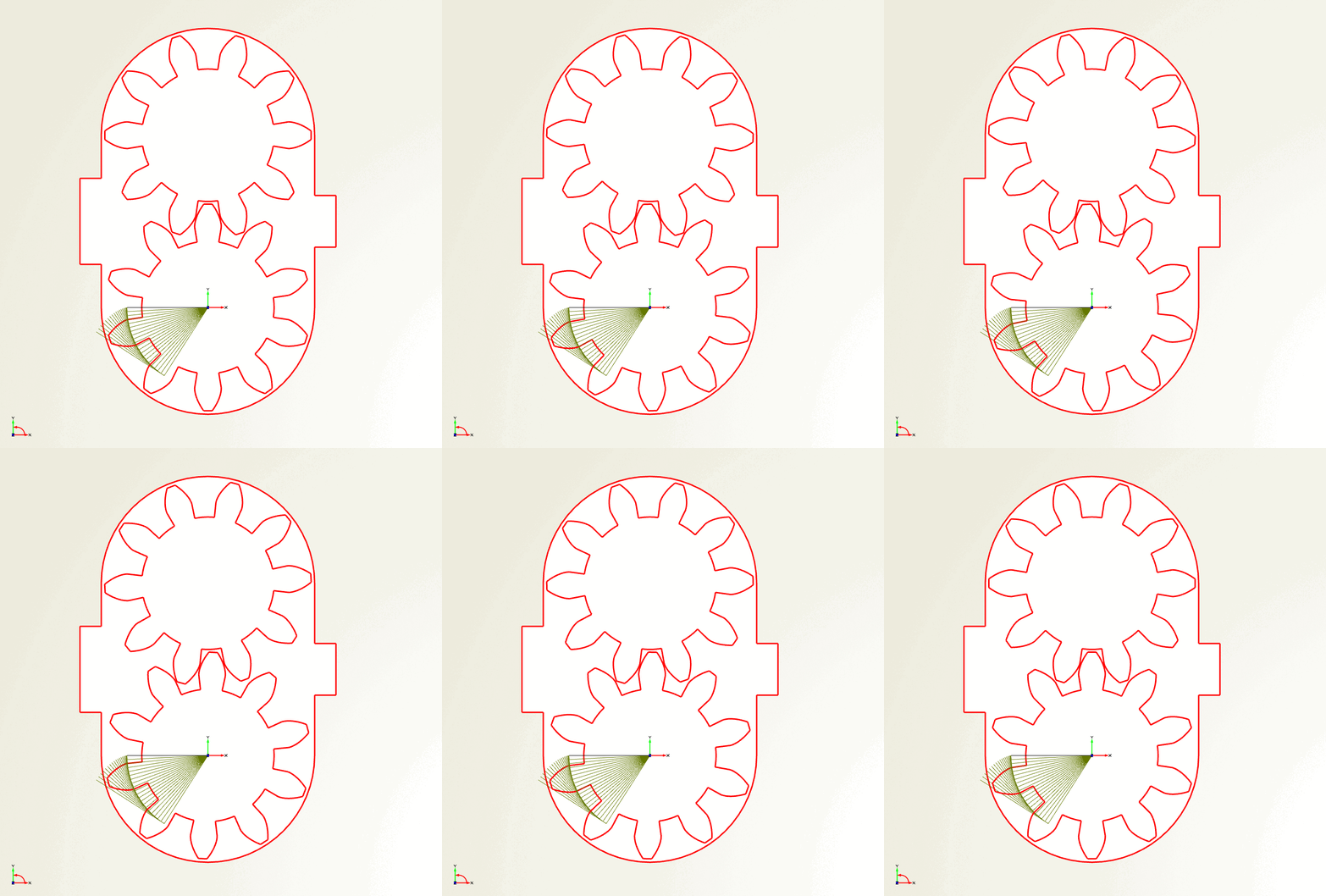
Finally, the outcome of the animation creator in CAESES® is given in the following pictures where a second gear is also given:
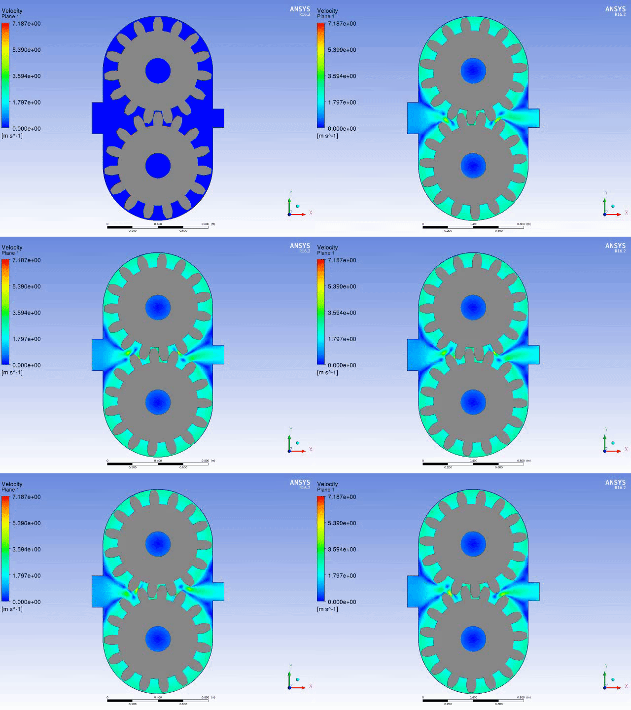
We conducted several simulations for the model where we systematically changed all the gear pump parameters. The result of one run is shown in the next animation. We checked the geometry and the corresponding flow behavior by creating a set of design candidates automatically with the design engines in CAESES®. The geometry creation process was completely robust and all simulations succeeded without any problems. So basically, our colleague had finished a setup that can be readily used now for design studies and shape optimizations of this application. Our customer is happy at this stage.
Next Steps
This first model was an interesting start for us to get into the optimization of these products. CAESES® really comes with the required method set to design these amazing products. The presented work is still in progress, but our colleague immediately started to explore different types of gear pumps. The last animation of this post shows parts of an internal gear pump, again modeled in CAESES® where the entire maths are wrapped in a feature definition.
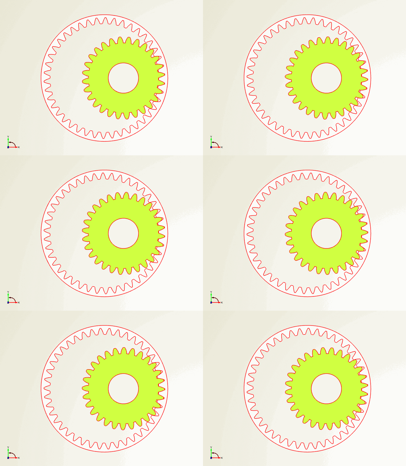


Variation of the number of teeth of the pinion, visualized in the design viewer of CAESES
More Information
We hope you have enjoyed this short blog post. Feel free to get in touch with us if you are interested in gear pump design and optimization. We are eager to explore things a bit more together with you!