Design Exploration and Optimization: Is Your CAD Tool Really up to the Task?

If you have been browsing the information on our website, you might have seen that our tool CAESES® brings along several different components, such as a CAD modeling environment, process automation, design exploration and optimization methods. Out of these it is, however, really the (very specialized) CAD modeling that is our main focus and strong point in the context of simulation-driven design. You, as well as several of your fellow engineers, might be wondering, “do I really need an additional CAD tool?”. Obviously, we think you do and here is why. But let’s start at the beginning…
CFD Becoming a Design Tool
Due to the rapid development in computer technology over the last decades, both in terms of computing power and affordability, the use of CFD has increased significantly. Not only is it being utilized to a much larger extent, but also earlier and earlier in the product development process. As opposed to using CFD late in the design process, where it can merely serve for validating a completed design or give some guidance for late changes, employing it early in the process turns it into a real design tool. It can be a valuable help in quickly gaining knowledge about the product’s behavior and, under strict consideration of the product’s performance, guide the design in the right direction from the start, when critical decisions are taken. Apart from the availability of computing resources, another factor that has greatly contributed to the increased use of CFD is the improvement in ease-of-use. While it previously was a tool that was mostly limited to being applied by simulation specialists, it is now available to designers and engineers at large. Especially the advances made in the automation and robustness of the meshing process have fueled this development.
Process Automation and Optimization
As a next logical step, applying CFD early in the process and considering its results to guide the development of the product, quickly leads to the wish of employing it within an automated process for the systematic analysis of design variants – design exploration – and optimization. Shape optimization of components and systems is becoming a standard procedure in many industries that deal with flow-related geometries, such as the automotive, maritime, aerospace and power generation industries. A common denominator in all these very different products is that small concerted changes in shape often lead to substantial improvements in performance. Furthermore, even small improvements often yield important benefits for the producer, the consumer and the environment, e.g., when reducing energy consumption and emissions.
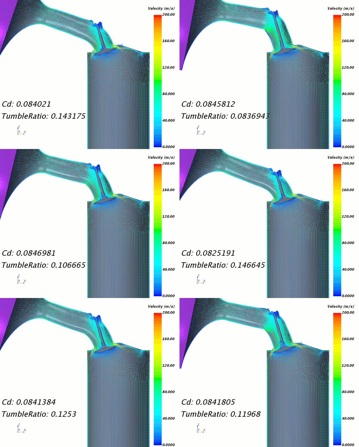
Automate CFD analysis for all geometry variants
Apart from the pure CFD tools that, as previously mentioned, are becoming increasingly suited for process automation, additional complementary CAE tools are needed, which take care of other tasks required for the complete automation of the process: control of the optimization process, including variant and data management, and generation of the geometry variants that should be evaluated, providing the input for the simulations. While there are quite a few generic optimization tools on the market that can fulfill the former role, the latter – i.e., dedicated tools for shape variation – seems to be a rather sparsely populated niche. Traditional CAD systems often do not fulfill the given requirements, well, at least when dealing with the complex, compound-curvature shapes that characterize many flow-related geometries, and a specialized CAD approach is called for instead.
The Bottlenecks with Traditional CAD Tools
Traditional CAD packages are surely very powerful systems that accompany the complete design process and fulfill many different tasks, e.g. constructing production-level geometry models, creating complex assemblies, producing BOMs and manufacturing drawings, as well as managing PLM data. They are, however, often detail-centric, meaning that the geometry models include many details that are relevant for the final product, but not necessarily for the simulation. When pre-processing the models for the CFD grid generation, they have to be de-featured, the “wetted” surfaces have to be extracted and the geometry has to be cleaned up (e.g., making it watertight). Also, these tools are often not predisposed for quick variation of complex geometry. Changing properties of the shape can involve a lot of manual effort and is not necessarily robust, leading to many infeasible variants when attempts are made to automate the variation.
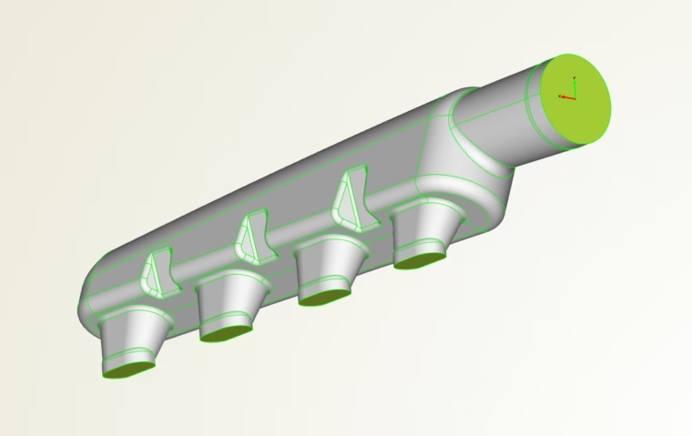
The automated regeneration of complex geometries is often a challenge for traditional CAD tools
Another aspect that characterizes traditional CAD is the typical user group. Usually, a dedicated CAD department will be in charge of operating the CAD system, handing over geometries to the CFD department. When the people in the CFD department want to try variations of the geometry or suggest some changes, they have to request a new geometry from the CAD departments, which often leads to delays and an inefficient process. Obviously, process automation is hardly possible in this set-up.
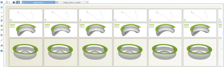
Efficient automated solutions are required to robustly create and also to assess large sets of design candidates
Design Exploration and Optimization: The Case for a Specialized CAD for CFD
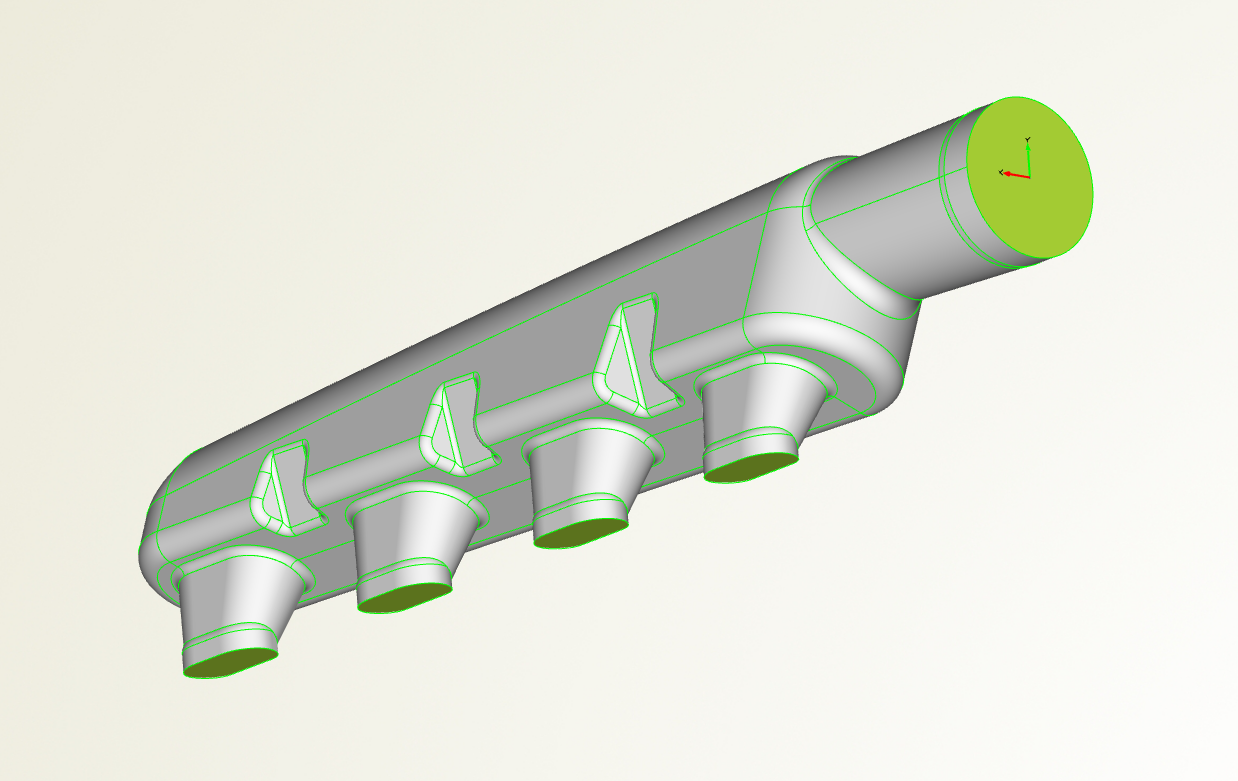
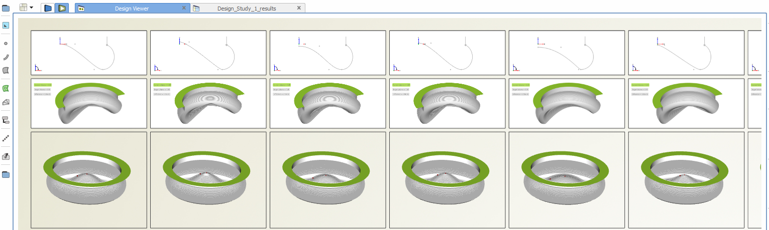
A specialized CAD like CAESES®, on the other hand, is a surface modeler that focuses on the modeling of the CFD-relevant geometry only, providing it in a state that can directly be used for simulation. It has a strong focus on geometry variation, so that, once a model has been parameterized accordingly, it can robustly provide geometry variants just by simply changing the model parameters, be it in a manual or an automated process.
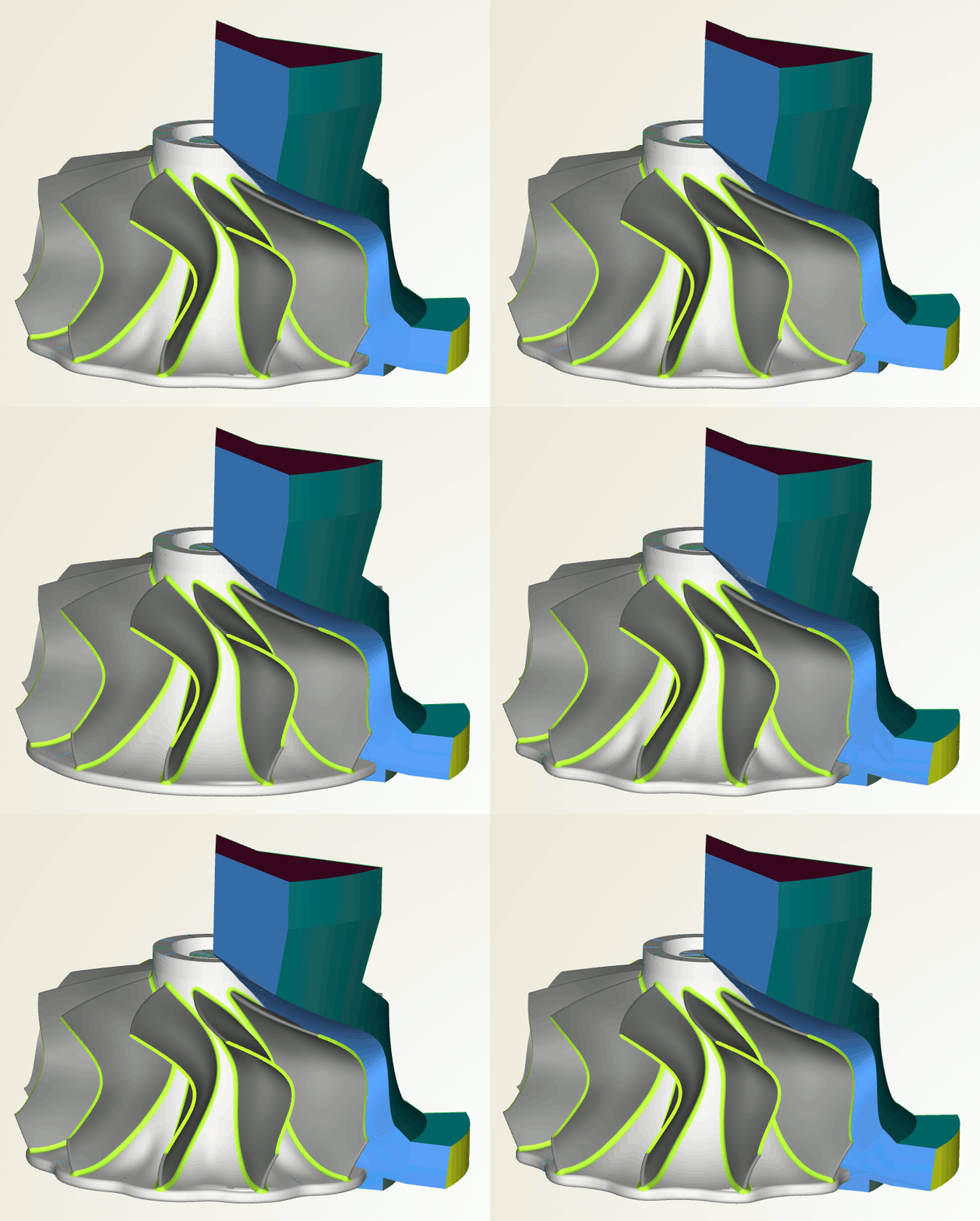
Parametric model of a turbine wheel including the periodic CFD flow domain
The requirements fulfilled by such a CAD tool for CFD can be summarized as follows:
- Geometries should be defined and controlled by as few parameters as possible, thus reducing the degrees-of-freedom. The optimization effort scales with the number of free variables (often in a quadratic fashion); therefore, a low number is highly desirable.
- It should be easy and fast to vary the geometry by controlling the values of previously defined parameters. These parameters should be independent from each other and it should not be required to change multiple parameters in a concerted way, just to obtain a specific change in shape.
- Geometry generation should be robust with a minimal amount of failed variants.
- The generated geometry should be provided in a state and format that can directly be used for the simulation tool involved in the specific process.
- The system should have the ability to manage constraints and even build them right into the model, so that the creation of infeasible variants is prevented or at least minimized.
In contrast to a traditional CAD package, this is meant as a tool for the CFD engineers, giving them the ability to generate their own geometries and variants, even at a stage where the design is not progressed so far that the CAD department can actually hand over geometry files.
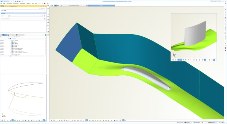
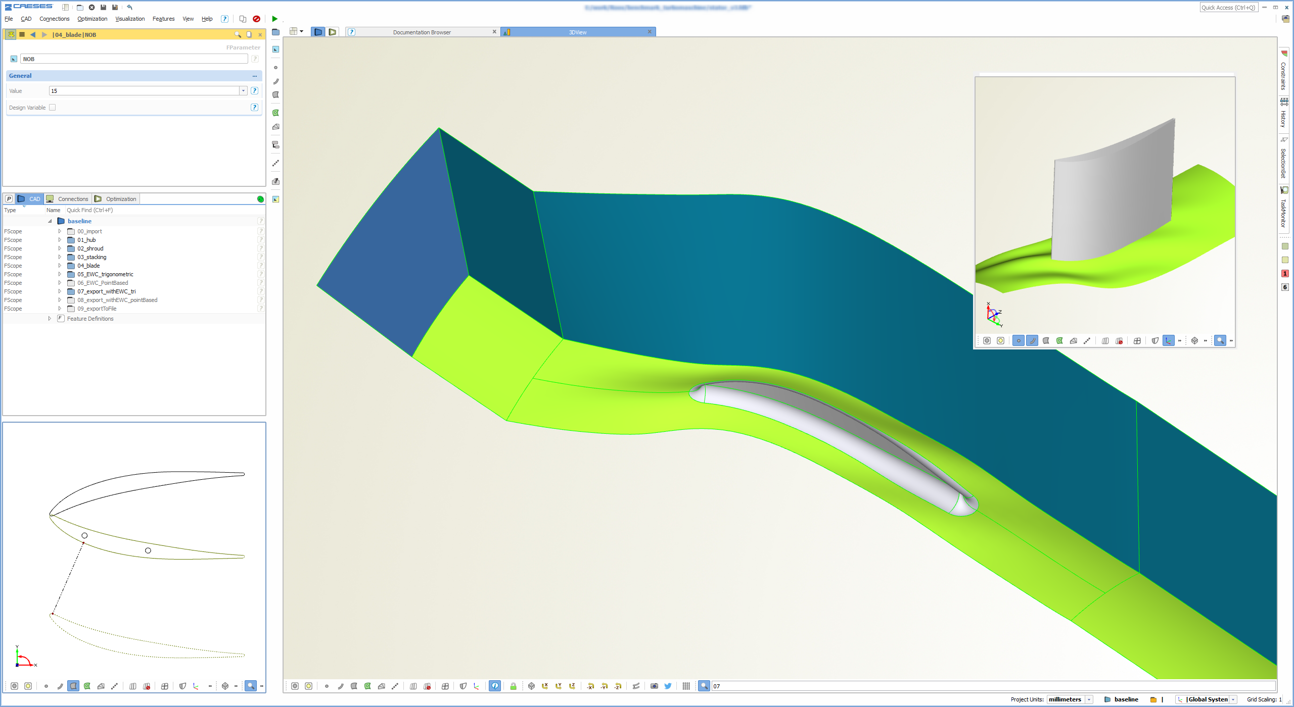
Parametric stator model including periodic CFD domain
What about Morphing Tools?
A typical alternative to using a CAD package in the design exploration or optimization process is a morphing tool. Such tools usually act in the CFD domain by deforming the computational mesh. While this does bring along some advantages related to removing the necessity for remeshing, it often creates problems downstream. The optimized geometry, that is now only existing in the CFD domain, has to be brought back to CAD, which usually means remodeling it, trying to stay as close to the result as possible. This takes substantial effort and often results in slight deviations from the optimized shape, with possible negative impact on the performance.
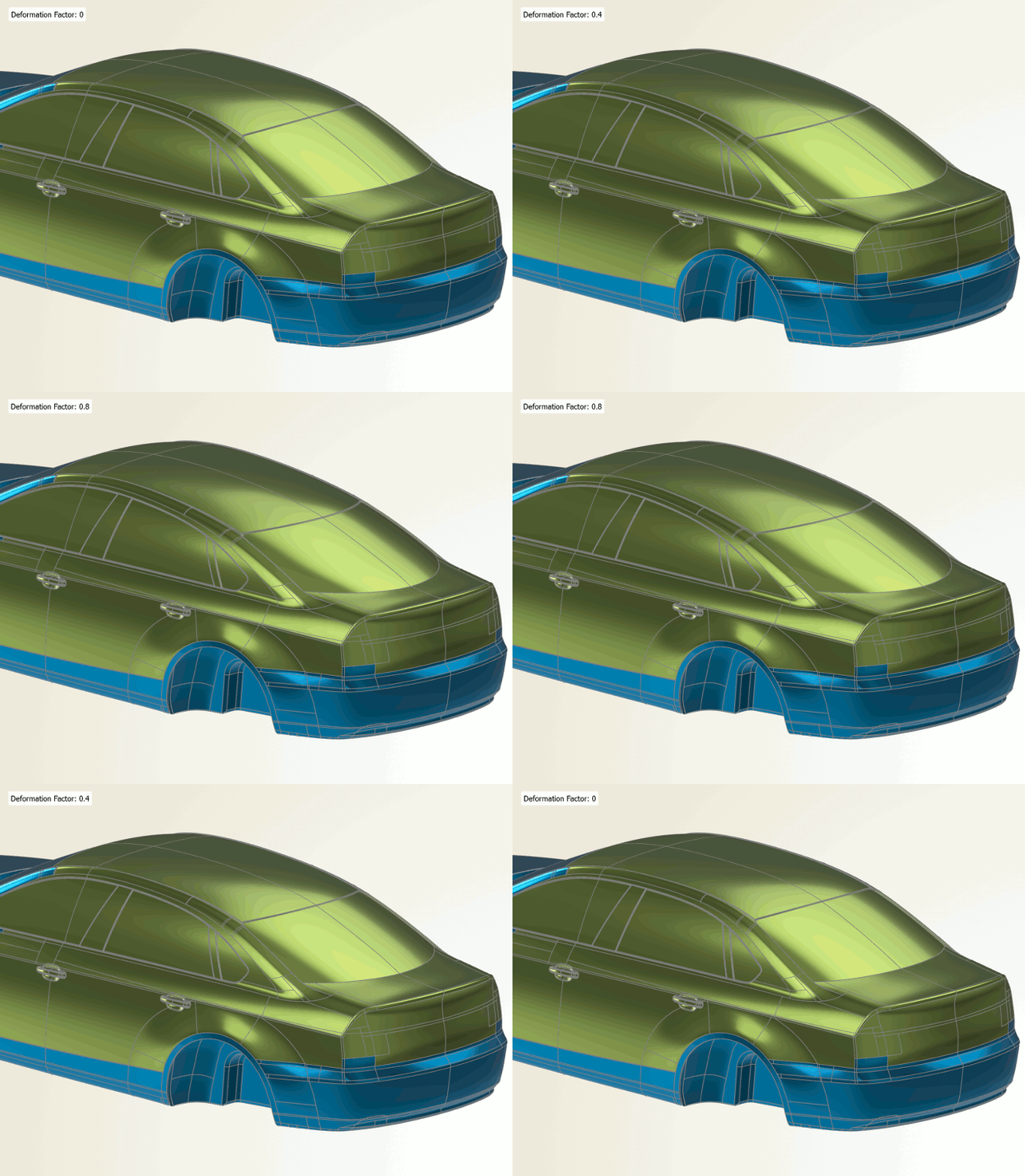
RBF morphing in CAESES: Deforming the back of the car geometry that is given e.g. as STEP/IGES file
CAESES® also brings along some powerful morphing capabilities to work with existing geometries, without having to build a new parametric model from scratch. The difference to most other morphing tools on the market is that it stays in the CAD domain, applying the deformations to the original surface geometry. After the optimization, this geometry can easily be exported in a standard geometry format and brought back into the production CAD system for further development.
Bottlenecks with Your Traditional CAD System?
If you have encountered one or more of the bottlenecks mentioned before, when using your traditional CAD package for design exploration and optimization, get in touch with us and find out if CAESES® is the right solution for you.