Automated Solid Generation for Structural Analysis at MTU Friedrichshafen
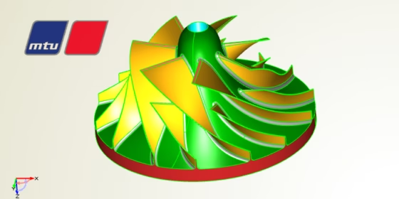
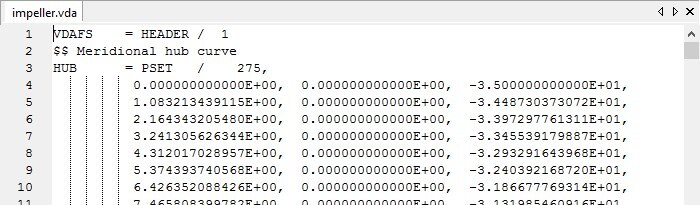
Some time ago, our customer MTU Friedrichshafen (the core entity of Rolls-Royce Power-Systems) approached us with a very interesting request. They design large turbochargers for diesel engines, and they use CAESES® for the design of volutes and other engine components. Some of their impeller designs were created by applying NUMECA software. In NUMECA Autoblade, such a model can then be exported using an ASCII format (*.vda), which basically contains point data for the meridional hub and shroud contours and the blade geometry. What they needed now was a very quick, single-click solution to create a solid body from this ASCII file, in order to conduct structural analysis for the impeller. The status quo had been that they already tried to semi-automate this process in a traditional CAD software. However, this step-by-step approach took them roughly 30 minutes for each design. The goal was to take this ASCII file and offer a fast and robust one-click solution in CAESES® to generate a solid body from this point data. The following screenshot shows a typical vda-file, which was our starting point:
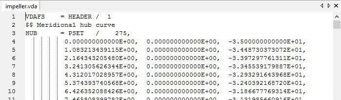
Example of an impeller vda-file, exported by NUMECA Autoblade
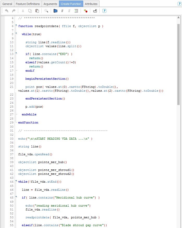
In general, a CAESES® user can define custom methods and functions, to read in and to parse files. For this purpose, so-called feature definitions are used. Basically, this is some kind of intuitive scripting environment where all CAESES® commands are available. We created a feature that opens the ASCII file, reads in the data and creates curves and surfaces from it. Here is a code snippet of this feature definition:
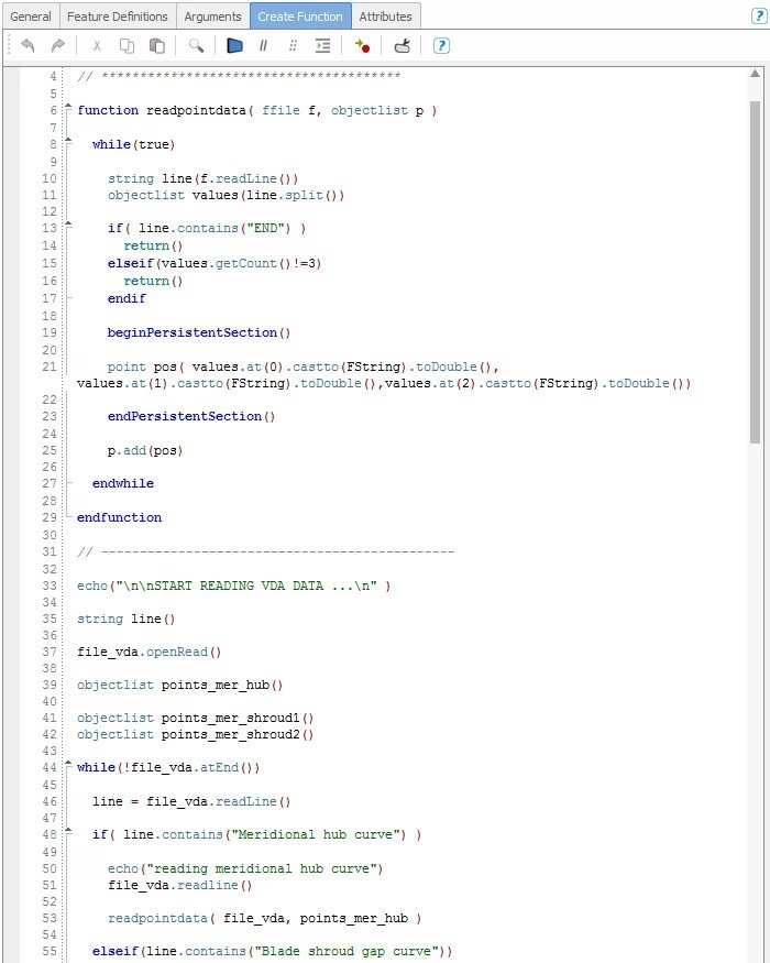
Feature definition to read in and parse the ASCII file
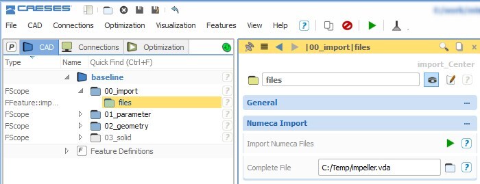
Feature definition to read in and parse the ASCII file[/caption] The only input for this feature is the ASCII file, which is set in the user interface of CAESES®. By clicking on the “import” button in the next step, the entire data gets loaded into CAESES®. Here is a screenshot of the user interface:
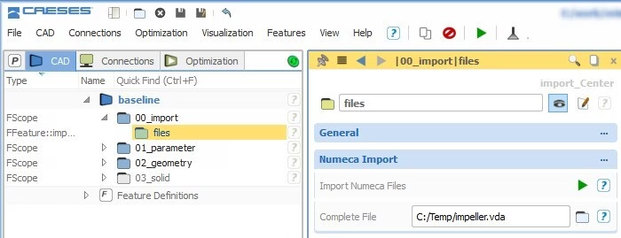
Ready to use: Set the vda-file and start the import by clicking on the green “run” button
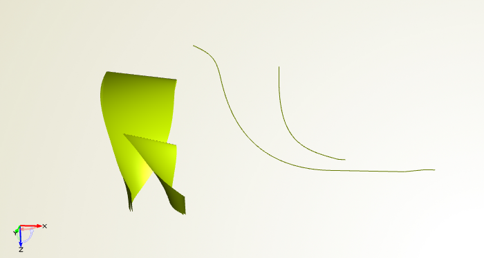
The first version of this feature code was ready in about an hour, and we were able to visualize the impeller data. This is shown in the next screenshot. In a second iteration, we further fine-tuned this setup by setting specific colors, and we implemented an automatic splitting of the leading edge region (to identify the leading edge location).
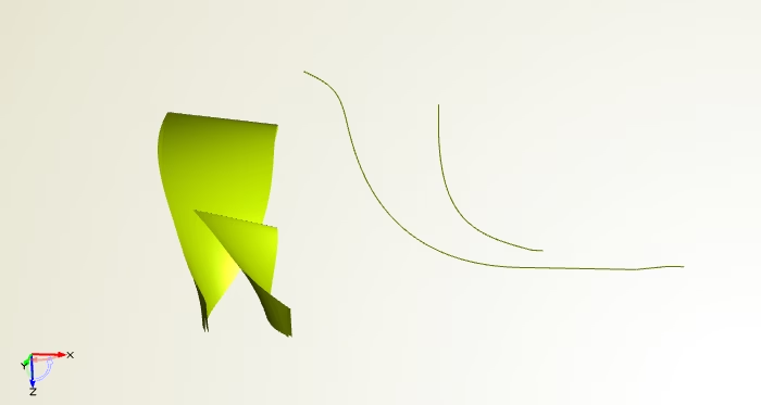
Imported impeller data based on the ASCII file content
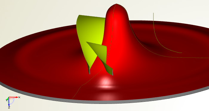
Imported impeller data based on the ASCII file content[/caption] In preparation of the upcoming solid model, we additionally created surfaces for the hub and shroud, as well as some kind of trailing edge that can be cut-off later on. This geometry can be simply written into the same feature definition by adding the corresponding creation commands. As a result, this geometry gets also automatically generated when clicking the “import” button.
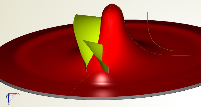
Additional surfaces that are used for creation of a solid body
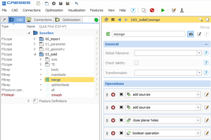
Additional surfaces that are used for creation of a solid body[/caption] The final step was to create the solid body for which we used a so-called BRep object in CAESES®. This object takes surfaces or solid bodies, and applies a set of operations such as Boolean operations, intersections and fillet generation. We added the blade as well as the hub and shroud surfaces, and applied several operations. Here is a screenshot of the BRep interface:
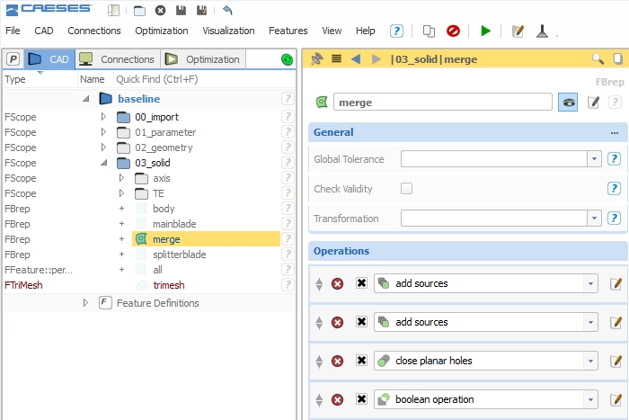
BRep object that creates a solid from the input surfaces, using a set of operations
The result of these operations is shown in the following picture — it is the geometry that is used for structural analysis. We colored all the surface patches differently, which is then automatically detected and used in the external simulation software.
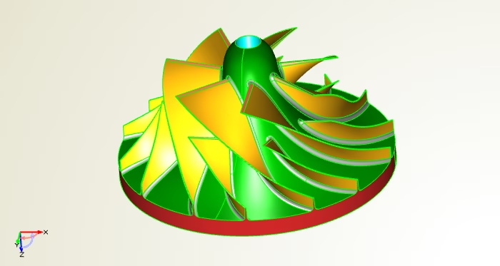
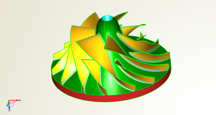
The final solid body for the strength analysis, including coloring
For the MTU engineers, this is now a single-click solution which saves them quite a lot of time. They simply choose a vda-file, click the “import” button and wait for a couple of seconds. That’s it. Finally, we implemented additional controls that are not covered in the ASCII file, such as the bottom plate thickness and shape, as well as the shaft diameter. For us, this was a very interesting and untypical CAESES® task – thanks to MTU for allowing us to publish this work.
“This amazing CAESES® setup saves us a tremendous amount of time, as well as tedious manual work! Thanks a lot to the guys of FRIENDSHIP SYSTEMS.” — Friedrich Fröhlig, Turbocharging and Fluid Systems, MTU Friedrichshafen (Rolls-Royce Power-Systems)
This amazing CAESES® setup saves us a tremendous amount of time, as well as tedious manual work! Thanks a lot to the guys of FRIENDSHIP SYSTEMS.
Friedrich Fröhlig
Turbocharging and Fluid Systems
More Information
Check out the quick guide about geometry scripting. The use of features where the entire command set of CAESES® is available gives you a powerful environment for custom tasks. Interested in what else you can do with CAESES®? Then check out the product pages or drop us a line if you have questions.