Variable Geometry for Endwall Contouring of Turbines and Compressors
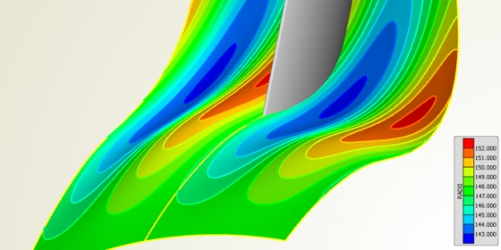
In our recent blog post about a parametric stator blade for the CFD-driven shape optimization, we mentioned that we had implemented an endwall contouring approach. The idea of this additional geometrical effort is to be able to modify the hub geometry, e.g. in the leading edge region of the blade, to minimize undesired secondary flow losses.
The following picture shows this demo stator model again, along with the 3D contours on the hub:
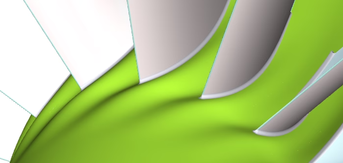
Endwall contouring for a stator blade
Endwall Contouring Approach
Basically, one can think about various modeling approaches to realize such a free-form shape around the blade. We have also used several different techniques in our customer projects. Most of the times the engineer is eager to reduce the number of free variables and hence reduce the computational time in CFD-driven optimizations. In the demo model of this blog post, we created an endwall contouring on the basis of trigonometric functions, i.e. sine and cosine waves. Such a periodic function is typically defined for a given axial location. The surface itself is generated by controlling and changing the 2D parameters of such a function while sweeping in axial direction. There are several variables to control the shape of the hub in this demo model, the most important ones are:
- Amplitude
- Axial location of maximum amplitude
- Phase shift at the start
- Phase shift at the end
A Short Demonstration …
The following video gives you a short impression of how the model works. Note that these design variables are changed manually, but they can be controlled automatically by optimization strategies. The rendering positions of the hub surface are colored according to their radial distance, measured from the center. There you go:
More Complex Endwalls
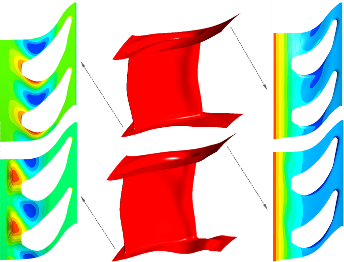
With such an approach, one can of course generate more complex shapes in optimization runs. The following picture shows a turbine blade where an endwall contouring was applied and optimized for the hub and shroud. The upper part shows a trigonometric approach as described in this post, while the lower picture shows a spline-based approach where control vertices were varied to find the optimal shape.
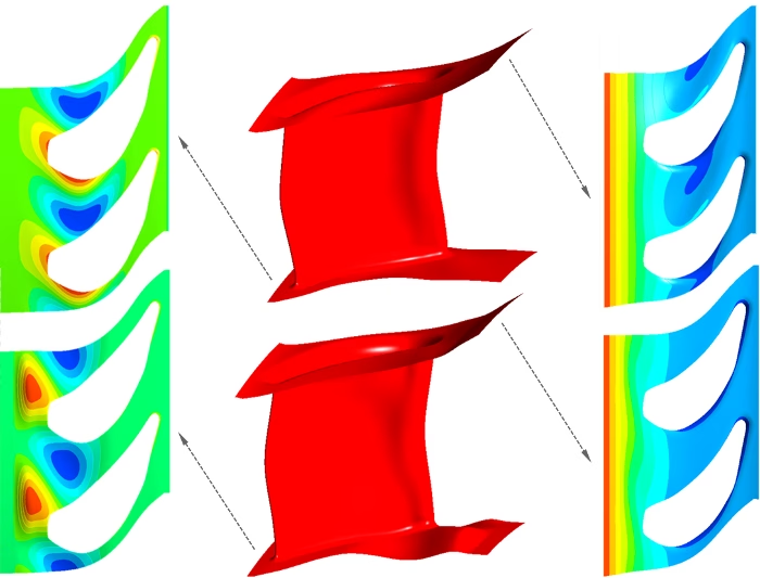
Complex endwall contouring for a turbine blade at the hub and shroud
More Information
We have also applied endwall contouring and other methods (e.g. for removing material from the hub due to stress and inertia considerations) to mixed-flow impellers. I.e. the parametric concept of variable hub surfaces is not limited to axial rotating machinery.
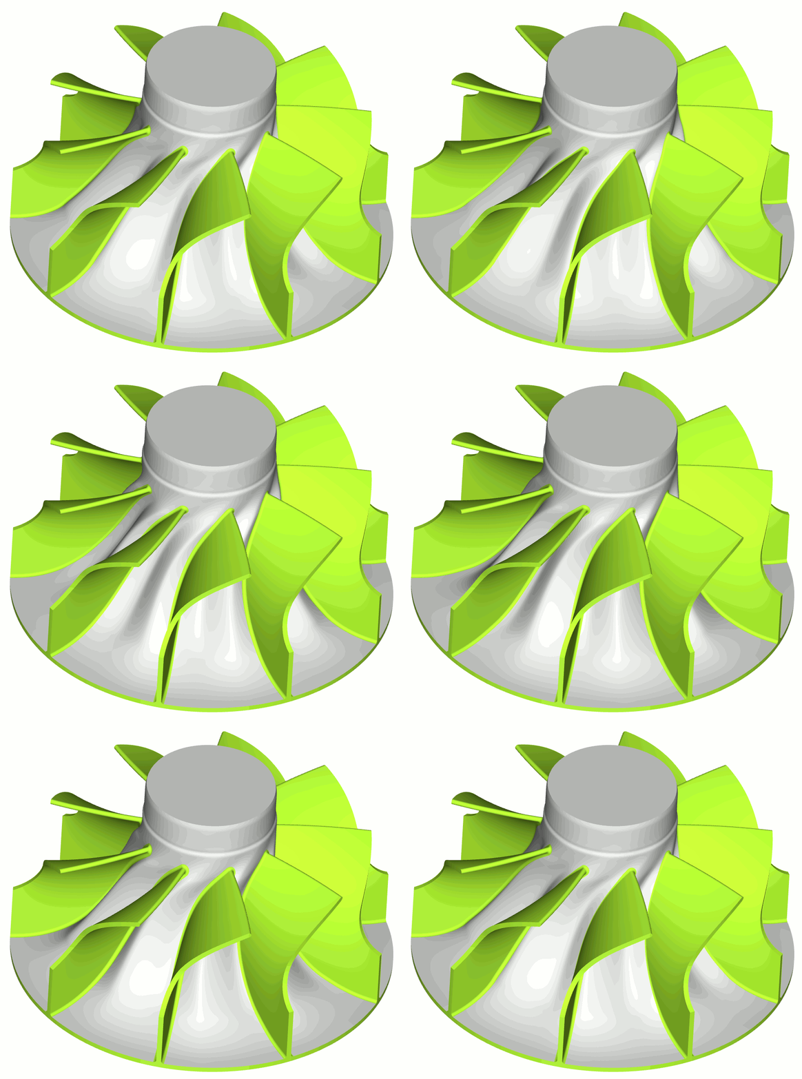
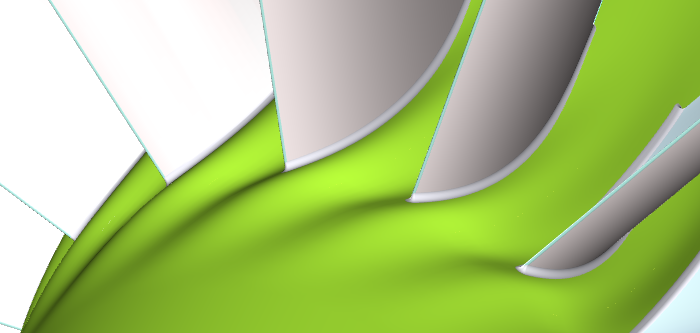
Hub profiling for radial turbines
Do you also design and optimize gas turbines or compressors that involve endwall contouring? Feel free to get in touch with us if you have any questions about this article. We are also fast in creating parametric models like the one above for your individual application in just a few days.
Follow Us
Are you interested in turbine and compressor design optimization? Then stay tuned and sign up for our newsletter to receive short reads like this one here! Don’t worry, we won’t bother you with too many emails. Of course, you can unsubscribe at any time :-)