Parametric Model of the TU Berlin TurboLab Stator
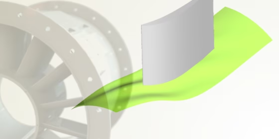
Efficient Geometry for TurboLab Stator Optimization
Some time ago, we were asked whether we can provide a variable and robust CAD model for the TU Berlin TurboLab Stator test case. This stator is installed in a measurement rig at the TU Berlin (Germany), and it was designed on a representative stator geometry as used in modern jet engine compressors. This means that the design has been investigated quite a lot, and hence the performance of the stator is well known (e.g. pressure losses across different operating conditions). With a suitable and flexible CAD model, one is able to run optimizations on this case in order to reduce the pressure losses even further. Since this is an ideal and interesting application for CAESES®, we decided to create such a setup.
The CAD Model
Our goal was to provide a variable stator geometry including a variable endwall contouring (EWC) parameterization that can be readily used for this optimization task. The model should be ready for meshing and CFD without any additional user interaction. This means that we also had to take care of the parametric periodic boundaries, including fixed definitions for the inlet and outlet (e.g. coloring or assigning patch names). We were able to come up with an initial parametric CAESES® model in a few hours. Basically, the shape of the stator can be designed with many degrees of freedom, and any kind of complex free-form shape is feasible as long as new design candidates fulfill a set of given geometry constraints. Check out this PDF which gives a detailed description of the design requirements. The main task was to consider these individual specifications. Here is a short overview of the stator’s manufacturing constraints:
- The number of blades is fixed to 15
- The axial chord of the blade needs to be kept constant
- Minimum thickness requirements for leading and trailing edge
- Thickness and distance constraints for two inner holes for fixing the blade
- Mounting constraints in terms of the plate dimensions
- Radii reduction limits for EWC.
All these constraints need to be addressed in the CAD model, to be able to generate feasible design candidates during optimization runs.
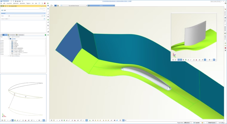
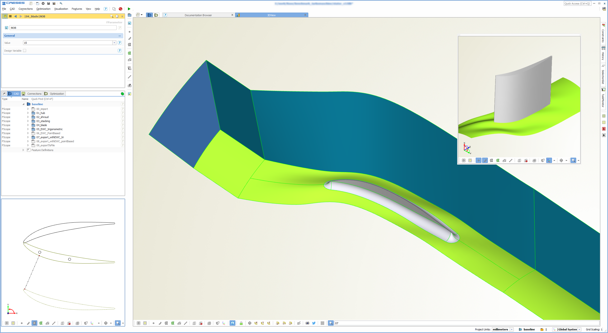
Parametric stator model including periodic CFD domain
The final CAD model in CAESES® gets controlled by a set of parameters for the blade and for the EWC. Most of the parameters are linked to distribution functions for the section profile, such as camber or thickness, that are allowed to vary radiall direction. When generating new design candidates by changing the model parameters, most of the geometrical constraints are automatically fulfilled. For this purpose, we embedded internal optimization routines that take care of some of the constraints. For instance, the positions for the two inner holes (to fix the blade) get automatically optimized for each design in an internal loop.
Model Variations
The following animations show quick changes to a set of parameters. The changes are rather large, just to give you an immediate idea of the the parameter effects. Note that the outlet angle is actually fixed in this benchmark test case i.e. you would not change the related parameters (however, our model contains this as an option, which is also visible in the animations). The first 3 animations show a single-parameter variation, while the last animation was created with 7 parameters. All animations were created within CAESES®.
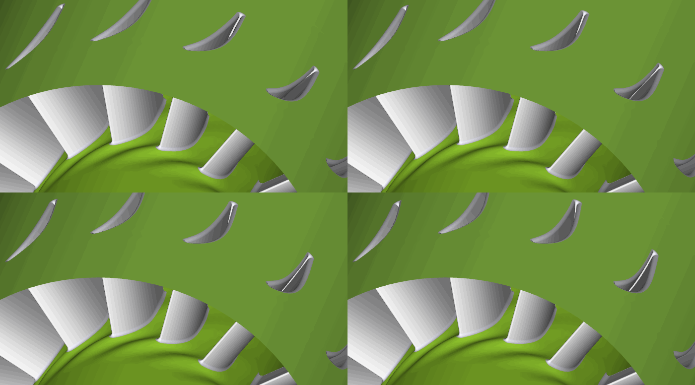
Variation of the camber angle
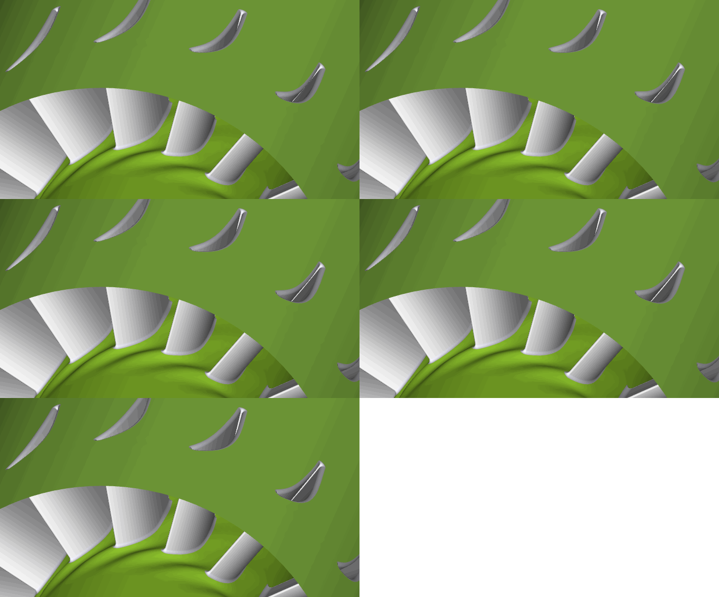
Variation of the thickness
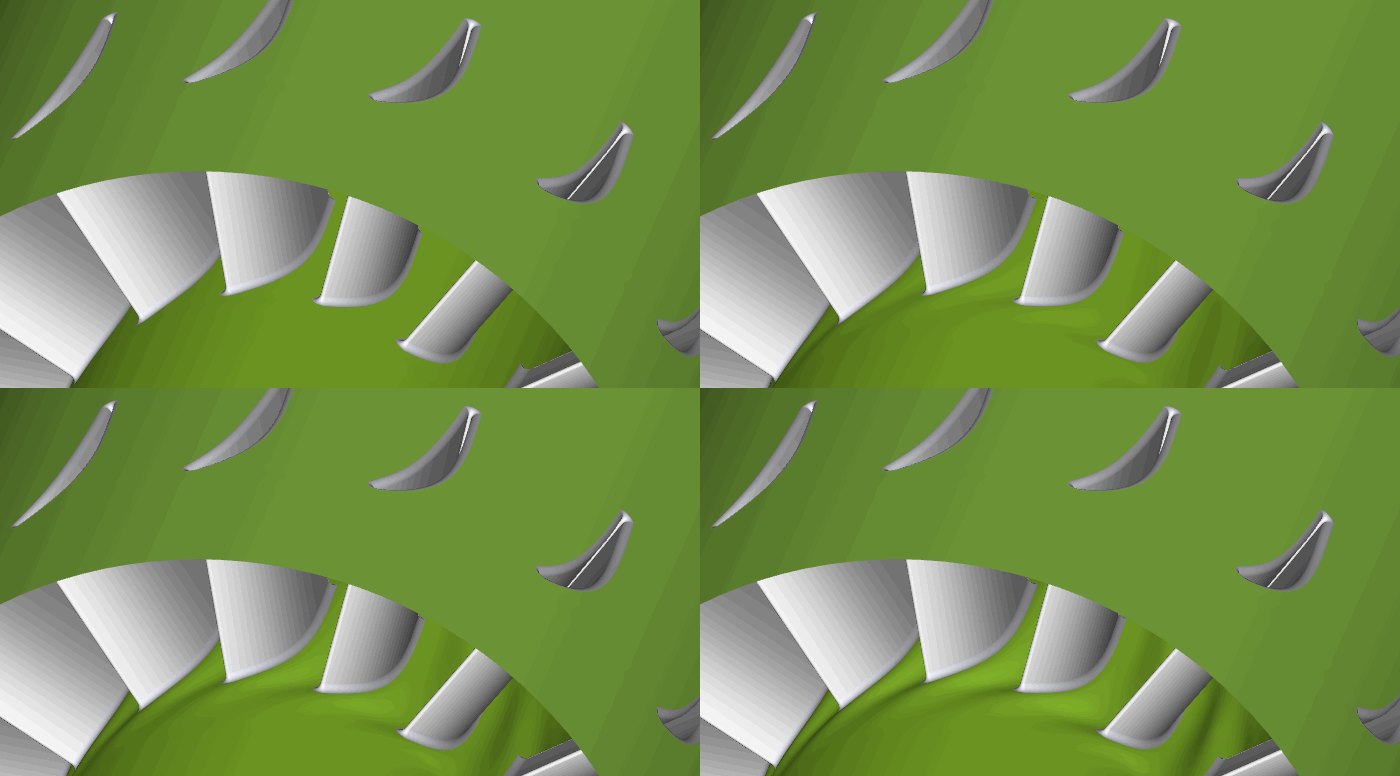
Variation of the endwall contouring

Variation of several parameters at once
Interested in the Model?
We think that this test case is a really great benchmark, and we decided to share this model with other parties that seriously intend to conduct an optimization for this TurboLab stator. Feel free to get in touch with us if you are interested in it — we are eager to see what you can squeeze out of it :-) Note that CFD-based shape optimizations with this model can be carried out by using the optimization strategies from CAESES®, in combination with your simulation tool of choice. Alternatively, you can make use of your own optimization tools where CAESES® runs in batch mode to generate new geometries. If you want to bring in your own ideas to this model, you can simply modify the blade and EWC parameterization — everything is open in our setup, and free to edit.