Released CAESES 5.2 — The Turbomachinery Special

The new CAESES release 5.2 was developed with a strong focus on turbomachinery design and is dedicated to users with the CAESES add-on Turbo. It offers a wide selection of components, workflows, and methods to simplify and streamline the parametric modeling of turbomachinery geometries, while maintaining the high level of freedom and customization that CAESES is known for.
Streamlined Turbomachine Workflow
The new turbomachine workflow provides both an extensive selection of dedicated design components, and a step-by-step guide through the geometrical modeling process of a fully-parametric turbomachine design. After setting the machine (compressor, turbine, pump or fan) and the flow type (centrifugal/radial or axial), the workflow streamlines the creation of every necessary geometry object and parameter, to help you create a powerful and flexible parametric model in less than half an hour.
The wizard-like approach supports beginners and advanced turbomachine designers in selecting and using machine type dependent features available within the add-on Turbo, keeping the project structure clean and organized, and making the modeling process faster.
Take a look at the tutorial video below to start getting to know the new workflow and learn how to design a parametric centrifugal pump in less than 20 minutes.
Airfoil Blade
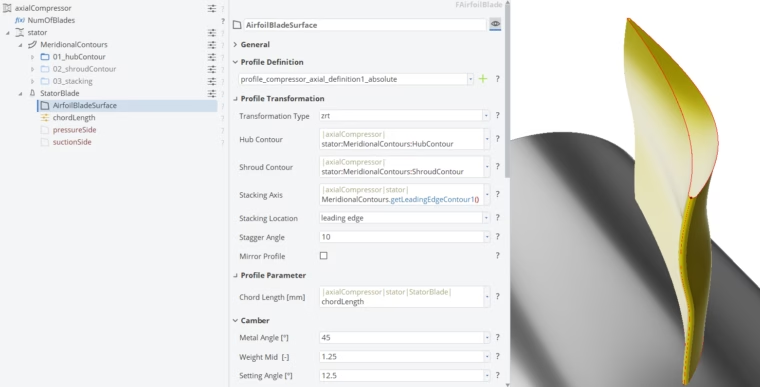
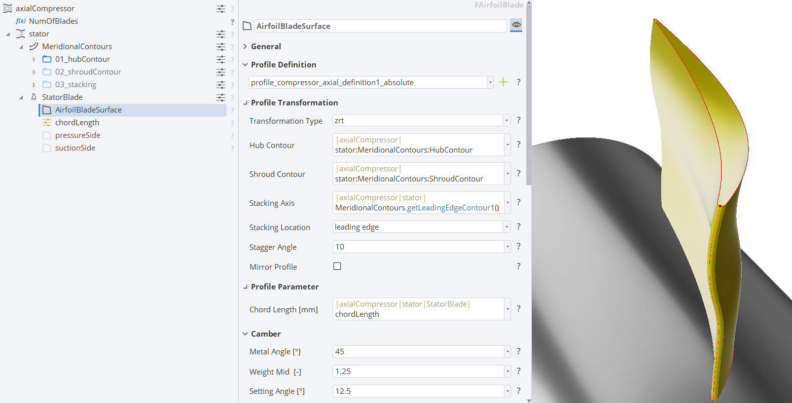
The new object type “Airfoil Blade” lets you create a fully-parametric blade based on an airfoil profile definition in a matter of minutes. It combines a 2D profile (feature) definition – either user-coded, or from a list of templates – with a 3D transformation to directly loft a surface in spanwise direction from hub to shroud.
Choose between
- a cylinder transformation, which transforms the 2D profile onto a cylindrical surface,
- ZRT (Z, Radius * Theta), which allows a transformation of a 2D profile onto a stream surface located between hub and shroud, where the x‑coordinate corresponds to the z‑position and the y‑coordinate corresponds to the radius*theta value,
- MRT (M, Radius * Theta) offers a transformation of a 2D profile onto a stream surface between hub and shroud, where the x‑coordinate corresponds to the meridional m‑position (streamwise arclength) and the y‑coordinate corresponds to the radius*theta value.
Airfoil Blade
Advanced Blade Fillets
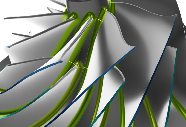
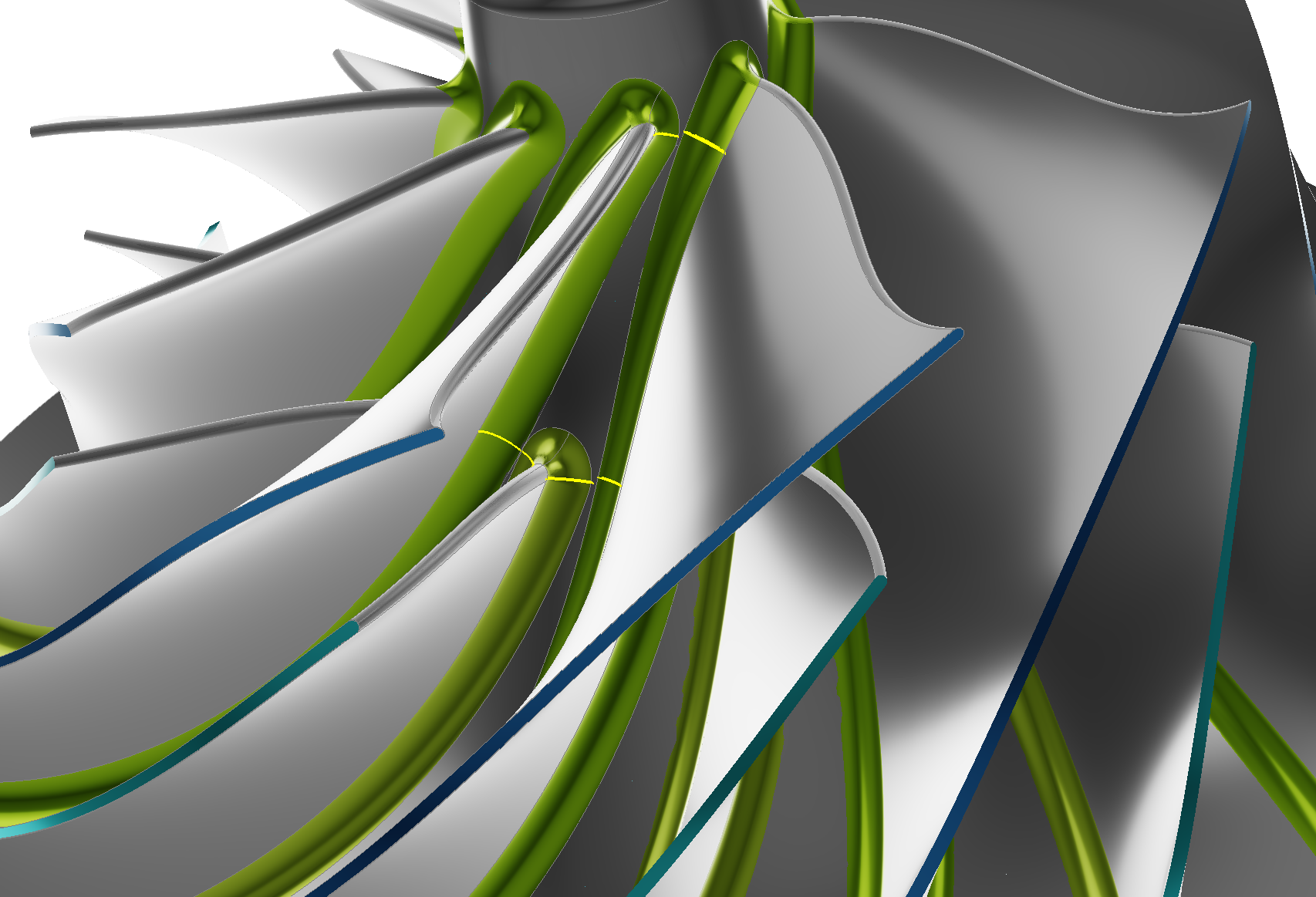
A great amount of development time has been spent on blade fillet creation. The new fillet object allows you to easily create constant or variable radius fillets and offers the option to include a boundary edge optimization to let the fillet run up to any specified boundary curve.
A special thanks to our users who gave feedback and many great suggestions through our helpdesk and forum!
Calculate the Maximum Fillet Radius
A new feature calculates the maximum fillet radius between two blades, which guarantees a 100% robust and smooth fillet creation.
Use the maximum feasible fillet radius or set your own value to create a robust fillet with a constant radius around the blade geometry.
Calculate the maximum feasible fillet radius between two blades
Variable Blade Fillet with Radius Distribution
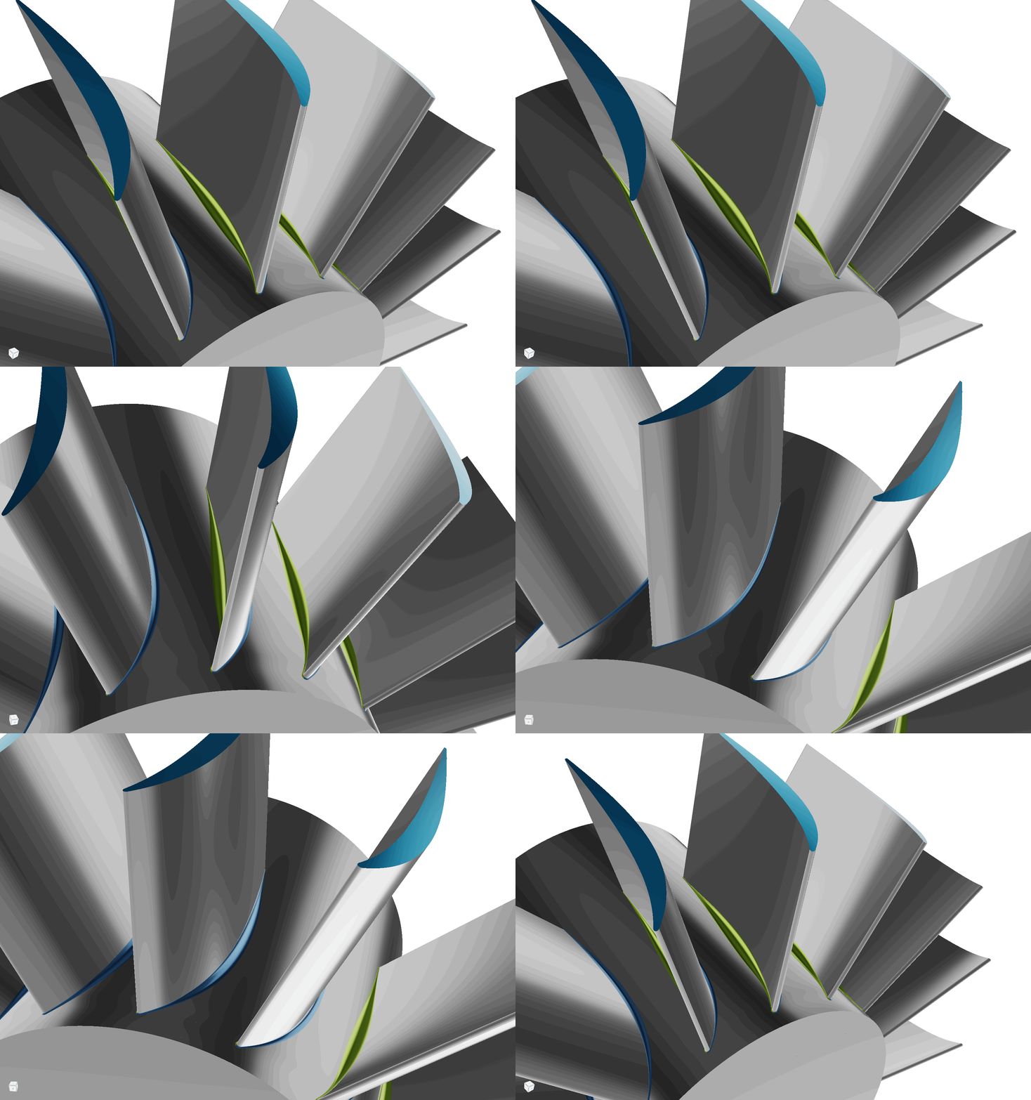
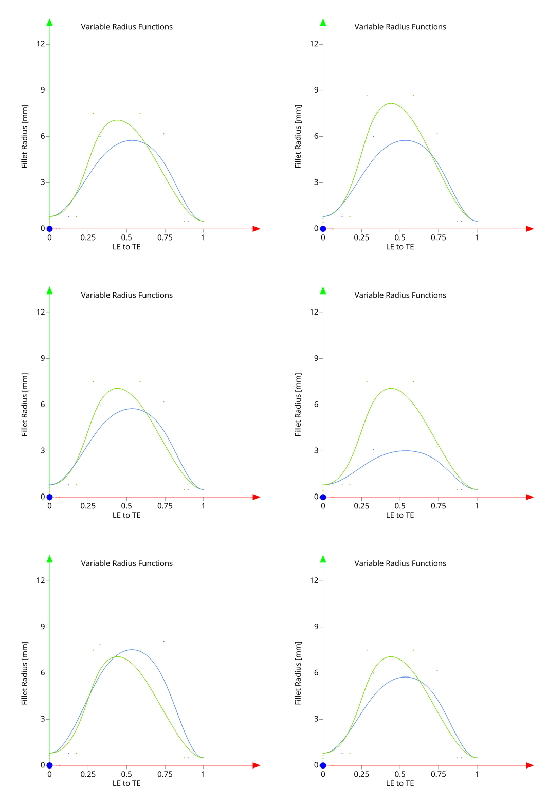
Define flexible radius functions to design the blade fillet with variable radius from the leading edge to the trailing edge for both sides of the blade.
Variable Blade Fillet with Boundary Optimization
Optimize the fillet radius to run up to a pre-defined boundary to avoid overlap.
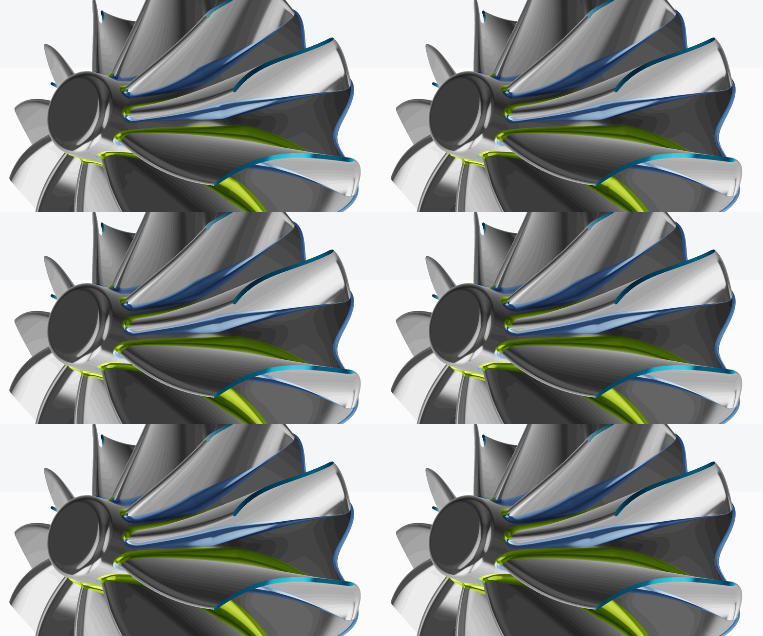
Animation showing decreasing distance to fillet edge boundary
Animation showing decreasing distance to fillet edge boundary
Analysis Tools for Blades
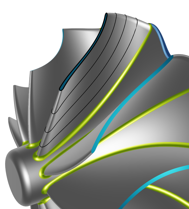
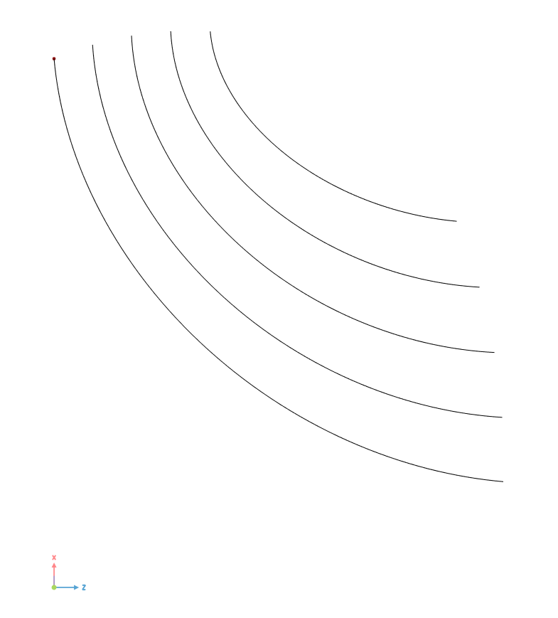
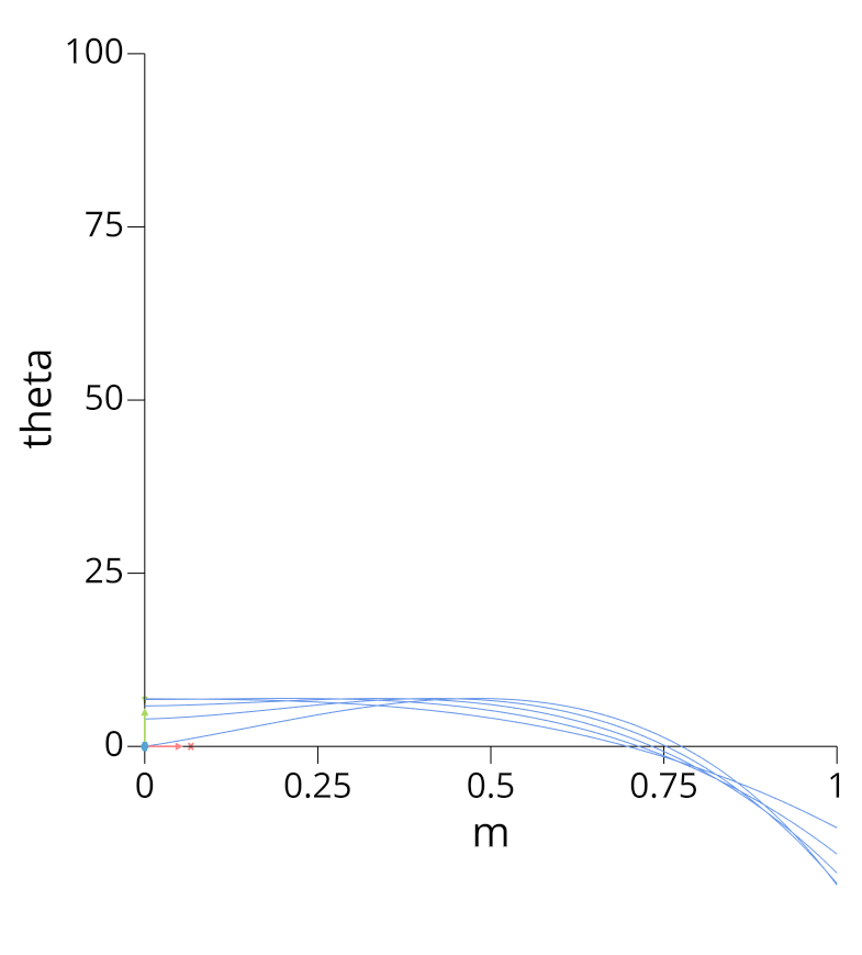
Quickly analyze any imported or existing blade geometry with the newly implemented analysis tools. You can now easily extract the mean camber surface, determine the blade and wrap angle (beta/theta) distributions, calculate the throat area between blades, or transform the 3D edges to the meridional plane. This toolkit allows you to quickly build a fully-parametric model from imported geometries.
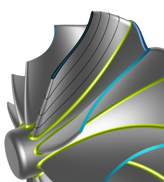
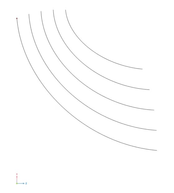
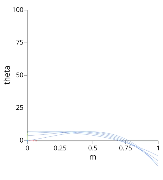
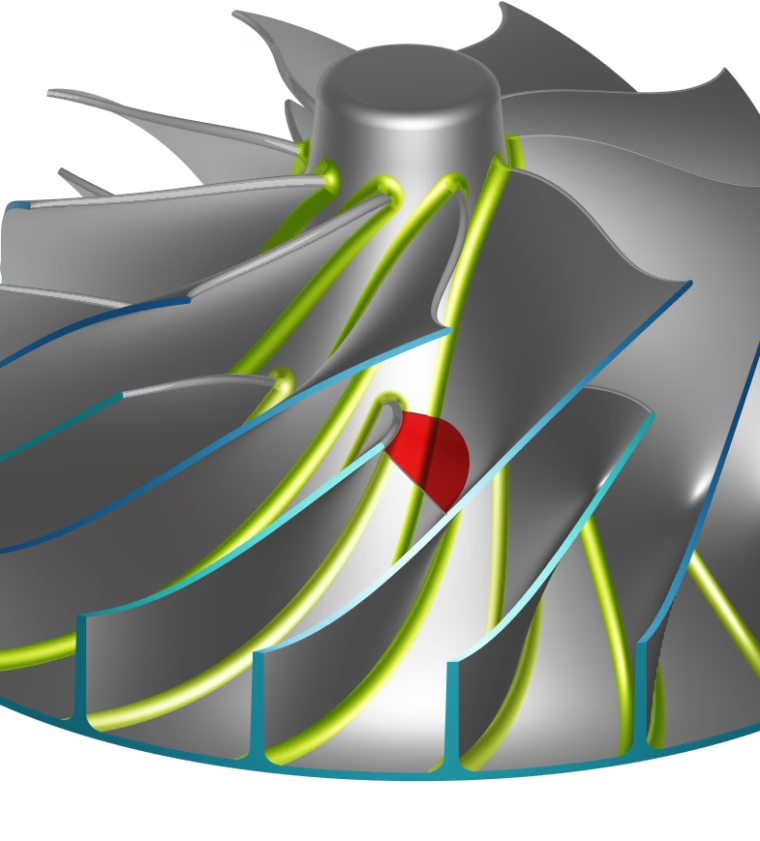
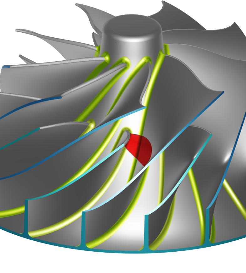
Throat Surface between Blades
New Turbomachinery Samples
New sample models for
- a centrifugal pump,
- a radial turbine with variable radius fillets and scallops,
- a centrifugal compressor including splitter blades,
- an axial fan,
- and an axial compressor stator with endwall contouring.
Webinar with Focus on New Turbomachinery Functionality
Join our release webinar on September 27, 2023, at 3:00 pm CEST and find out more about the new turbomachinery functionality in CAESES 5.2 that simplifies and streamlines your work, to facilitate the parametric design of turbomachines.
And So Much More!
What else is included?
- Render individual BRep faces transparent.
- New commands to quickly calculate the angle and radius of a point in cylinder coordinates.
- Improvement in the Ansys FLUENT ACT App.
Check out the change log for all details and get the latest version today!
Follow Us
If you are interested in updates about CAESES®, then sign up for our newsletter. Don’t worry, we won’t bother you with too many emails. Of course, you can unsubscribe at any time :-)