Quick Guide: Blade Geometry Export for ANSYS TurboGrid
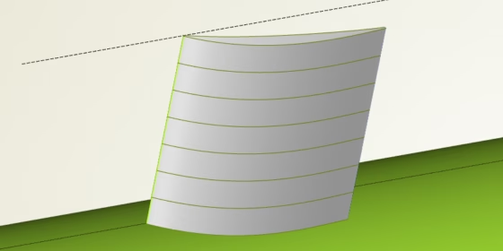
Do you design turbomachinery blades in CAESES® and you want to make use of ANSYS TurboGrid for meshing the variable geometry? Then check out the following quick guide which shows you the export procedure. It’s super fast and easy! Such a setup is directly ready for highly automated shape optimization workflows.
Where We Start From
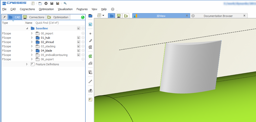
Let’s assume we have a parametric blade model in CAESES® where we can change all blade characteristics by a set of design variables (e.g. chord, camber, thickness distribution etc.). No matter if you consider a centrifugal or axial blade — as a result, we receive a single blade surface:
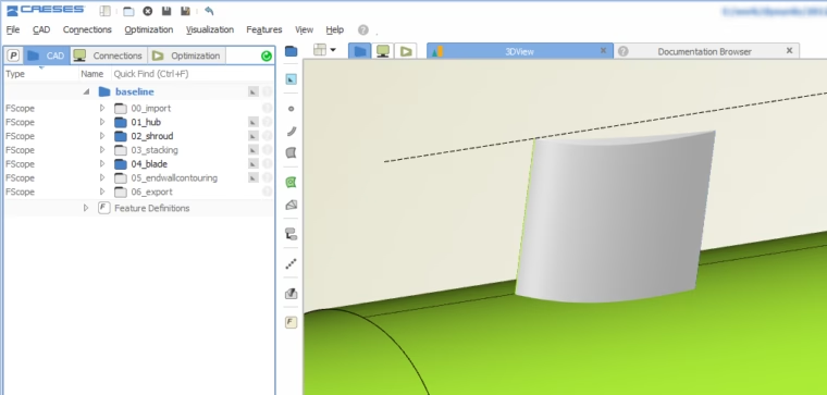
Parametric CAESES blade model
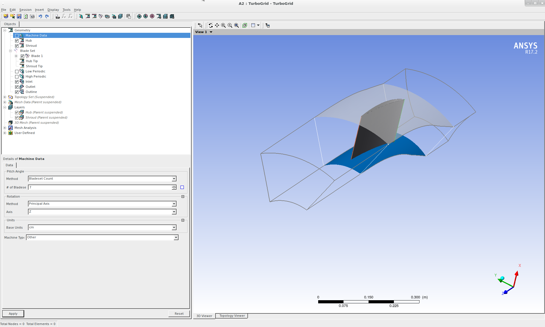
Our goal is to automatically create *.curve files which can be used by TurboGrid. Here is an example where *.curve files have been imported into TurboGrid:
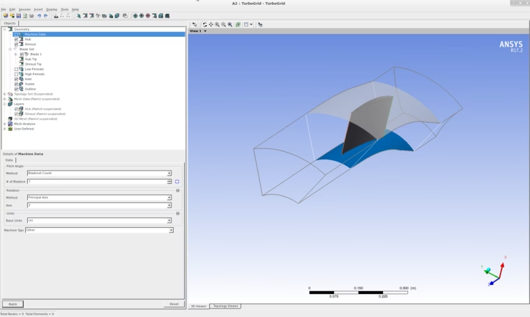
Blade imported by means of *.curve files
Step 1: Add the Export Features
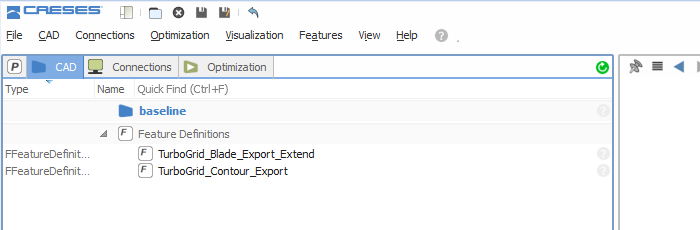
We need functionality to convert the blade surface and the meridional contours into *.curve files. These features can be downloaded e.g. from the public forum. We also offer maintained feature definitions, just get in touch with us. All you need to do is to simply drag & drop the TurboGrid export features into your CAESES® project. They will appear in the node “Feature Definitions”:
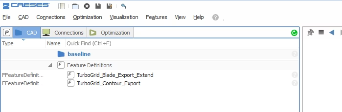
The export features can be found in the feature definition node
Step 2: Configure the Blade
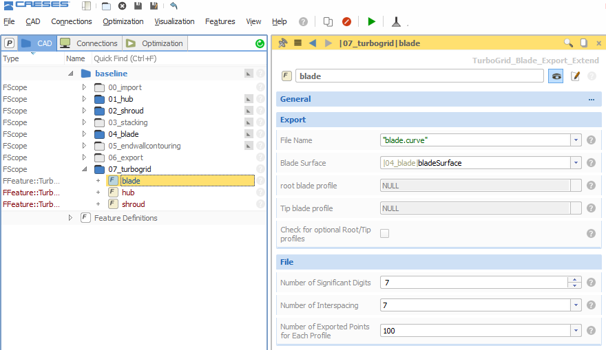
Create and select the blade feature. Set a name and choose the parametric blade surface from your project. The number of sections and number of points per section can also be set. That’s it for the blade.
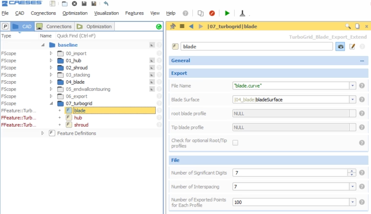
Configure how to export the blade
Step 3: Configure Hub and Shroud
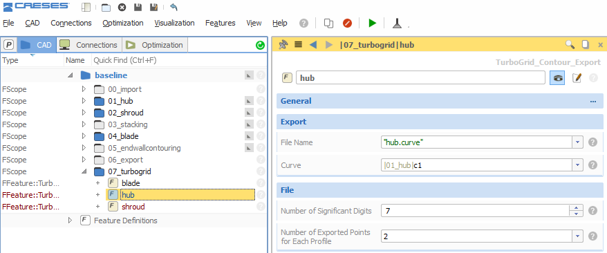
Create and select the TurboGrid contour feature. Set the file name and the hub curve as well as the number of points per section. Do the same for the shroud.
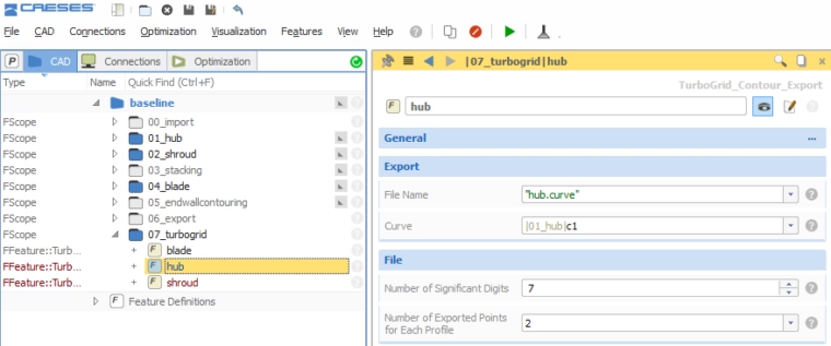
Set the file name and hub curve (here: "c1" is the hub curve which is just a simple line in this example)
Step 4: Run the Export
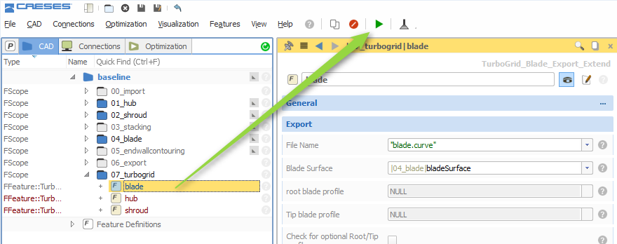
Now it’s time to trigger the export manually: Just select each feature and click on the “run” button at the top of the window. When you run the blade export, the sections are created and visualized in the 3D view. The export files (blade.curve, hub.curve, shroud.curve) are automatically put into the current design directory of the CAESES® project. This is convenient if you do studies since these files are then stored in the corresponding design directory of the variants.
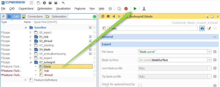
Simply click the "run" button for the export feature.
Step 5: What about Automation?
If you would like to automatically generate geometry variants of your blade along with the corresponding *.curve files, then you simply trigger these features in the design engines as a design post-processing step. Learn more about design engines … If you use your own optimization tools (optiSLang, Optimus, ModeFrontier, Dakota, …), then run CAESES® in batch mode and add the run-commands to your fsc-script:
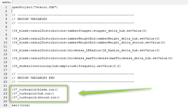
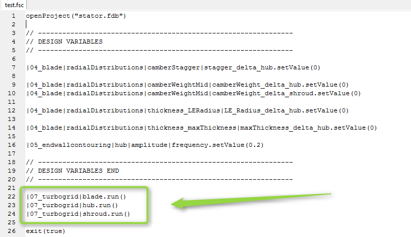
Script for running CAESES in batch mode: the run() command executes the export after setting the design variables
Follow Us
Are you interested in CFD-related topics and design optimization? Then stay tuned and sign up for our newsletter to receive short reads like this one here! Don’t worry, we won’t bother you with too many emails. Of course, you can unsubscribe at any time :-)