Propulsion System Intake Duct for High Mach Number Regimes
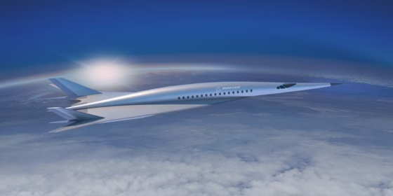
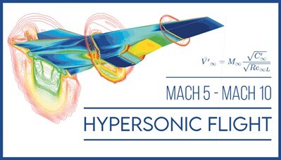
Since the Wright Brothers first took to the skies over 100 years ago, the world has been completely transformed and made to feel a whole lot smaller, where we are able to fly to all corners of the world efficiently and affordably. In recent years commercial flights have topped over a billion passenger flights per year. Now we are on the cusp of another major revolution with massive increases in flight speed and altitude. With high supersonic speeds or even hypersonic speeds exceeding Mach 5 at altitudes of 90,000 ft or more, it would be possible to fly from the UK to Australia in 4 hours, and this amazing feat may be commercially viable within 20 years.
Even more impressive is the development of spaceplanes that will bridge the realms of air and space. These vehicles would make use of air-breathing reusable propulsion systems, which would be capable of conventional runway take-off and landing, while during flight they would accelerate to hypersonic speeds to climb to low-earth orbit much more affordably than current single-use rocket systems. Applications ranging from payload delivery, surveillance and reconnaissance, or even space tourism are the driving forces behind these remarkable developments.
Hypersonic is like supersonic on steroids. Whereas supersonic speeds are defined as those exceeding the speed of sound (Mach 1), hypersonic speeds are in the regime at which intense aerodynamic heating causes molecular dissociation and ionization, typically above Mach 5.
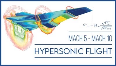
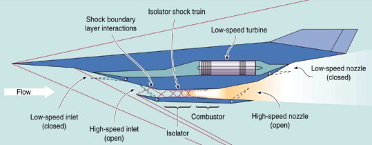
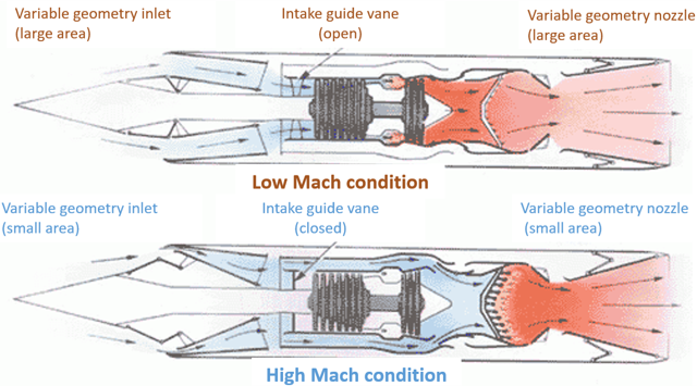
The propulsion systems required for these extreme conditions not only must operate in very challenging environments but the technologies used for relatively low speed flight (as during take-off and climb) are drastically different and often incompatible with those at high supersonic and hypersonic cruising speeds. Various combined cycle concepts that include conventional jet engine configurations with ramjets or scramjets or even with rocket stages have been on the drawing board and are now under development. One such propulsion system is the turbine based combined cycle (TBCC) which combines a conventional turbojet with ramjet or scramjet modes at high Mach numbers.
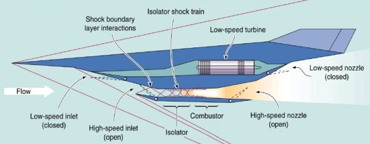
Turbine-based combined cycle propulsion system
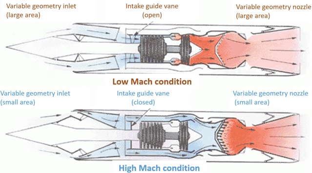
Turbine-based combined cycle propulsion system
Intake Duct Design with CAESES
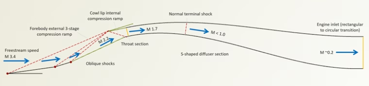
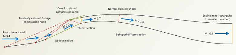
The present case study investigates a hypothetical intake duct geometry for a TBCC propulsion system, which channels high-speed air from the freestream into the engine and converts the dynamic energy into high pressure by making use of a series of compression shocks. The flight speed is set to Mach 3.4 in this study.
The duct design has a rectangular inlet with 3‑stage compression ramp upstream of the inlet cowl which gives rise to a series of oblique shocks that decelerate and compress the flow. Downstream of the inlet cowl is a diffusing S‑duct with an area expansion ratio of 2.18 which further decelerates and compresses the flow through a terminal shock and additional diffusion in the expansion zone. The duct transitions from a rectangular cross section to circular one at the engine inlet.
Intake duct geometry in CAESES
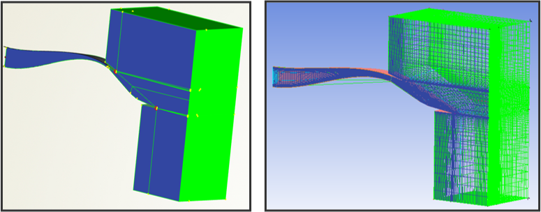
The model was created in CAESES with its specialized geometry engine for accurate, flexible, and robust geometry creation specifically geared towards automated design studies. In this case, the design variables were related to the lengths and angles of the 3‑stage compression ramp. The total deflection angle of the 3 stages was fixed and the 2nd and 3rd stage angles could be adjusted. Furthermore, the angle of the cowl lip could also be varied.
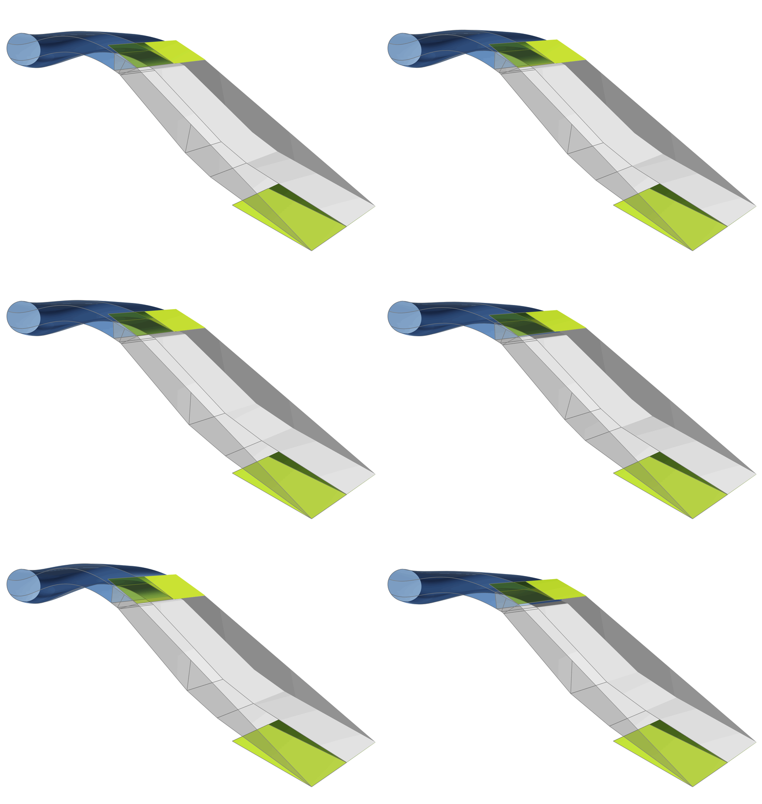
Intake duct variation
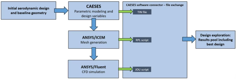
Workflow with CAESES and ANSYS
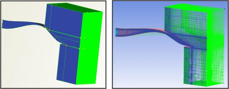
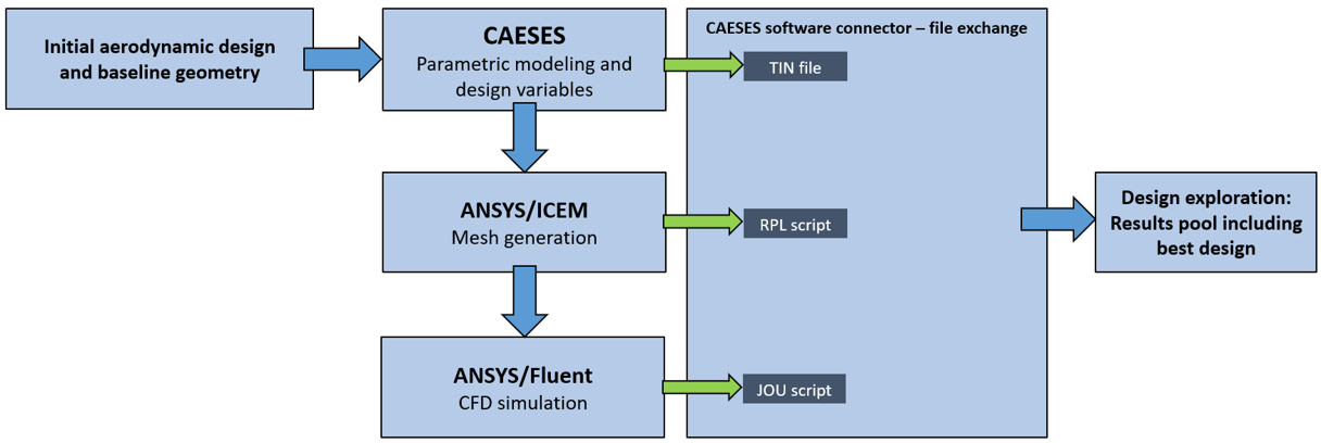
CAESES is also an automation and integration platform that can coupled to 3rd party tools to drive them in an automated workflow. In this study, CAESES was coupled to ANSYS/ICEM and ANSYS/Fluent for 3D meshing and CFD simulation respectively. To facilitate a streamlined workflow, CAESES also provided auxiliary geometries representing the flow domain upstream of the duct, as well as control points and surfaces that facilitated easy structured mesh creation by ICEM.
Results
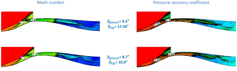
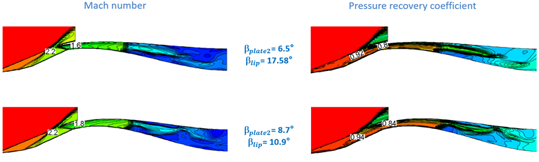
In this study, a design exploration (DoE) on 20 designs was performed using the CAESES built-in SOBOL algorithm. It was found that the angle at the cowl lip (βlip) and the resulting shock strength at that location had the strongest influence on the pressure recovery of the duct. Out of the 20 designs, the best case was found to have a reduced lip angle relative to the baseline of 6.68°. For this case relative to the baseline, the pressure recover coefficient at the throat increased by 6.3% (0.844 vs 0.794) and at the outlet it was increased by 3.9% (0.504 vs 0.485).
This example study has illustrated how CAESES coupled to ANSYS tools is very effective at establishing an automated workflow to explore and improve the design of a high Mach number intake duct for a hypothetical TBCC propulsion system. Most importantly, CAESES is ideal for automatically generating design candidates very precisely and robustly for complex duct shapes.
We would like to thank Nanjing Tianfu, the CAESES distributor in China, for providing the data and results that form the basis of this case study.

Contact Us
CAESES is used by several leading aerospace companies for various aerodynamic design and optimization projects. To learn more about how CAESES can benefit your organization for aerospace and aerodynamic applications, please contact as at info@caeses.com.
Image sources:
https://www.popularmechanics.com/flight/a21948533/boeing-hypersonic-passenger-plane-concept/
https://en.wikipedia.org/wiki/Hypersonic_speed
https://www.sciencedirect.com/topics/engineering/combined-cycle-engine
https://www.researchgate.net/figure/Configuration-of-a-mixed-compression-2D-hypersonic-inlet_fig10_273882611