Optimization of a Globe Valve with CFD in the Cloud
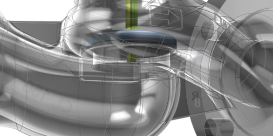
CAESES has an extensive pedigree in the optimization of valves of any kind. The aims of this project, which was carried out in cooperation with GEMÜ Gebr. Müller Apparatebau and SimScale, a German valve manufacturer and world leader in valves for sterile applications, and a leading provider for engineering simulation in the cloud, respectively, were twofold: exploration of the potential and possible avenues for improvement of a valve, and integration of SimScale as a cloud-based CFD solver in the process.
Subject and Goal of the Optimization
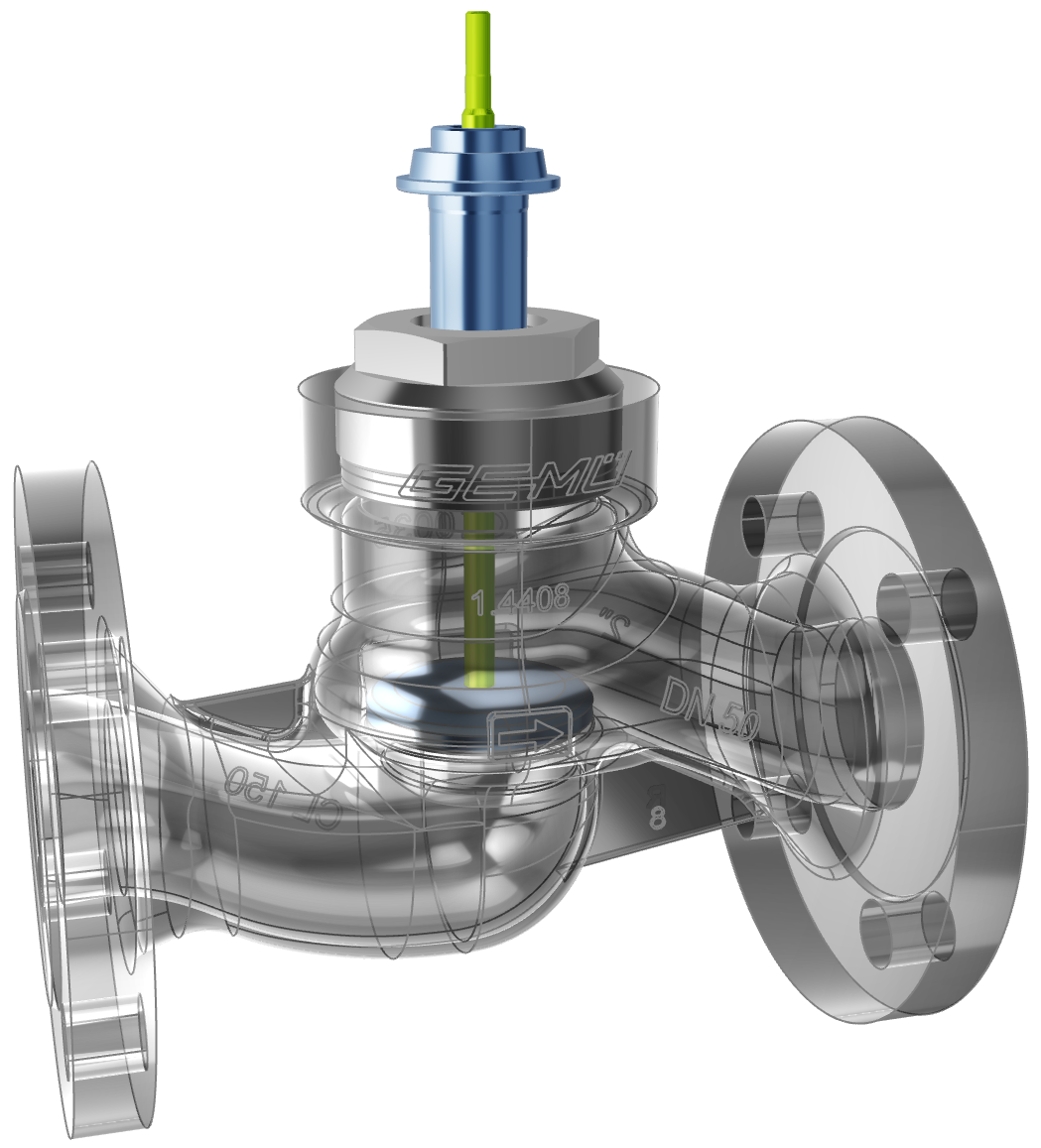
The subject of the optimization was the GEMÜ Globe Valve 534, a pneumatically operated globe valve with a metal body and plastic piston actuator that can be operated as a shut-off or control valve. It is used in industrial applications with non-aggressive media, such as water treatment, mechanical engineering and processing, power generation, and environmental engineering.
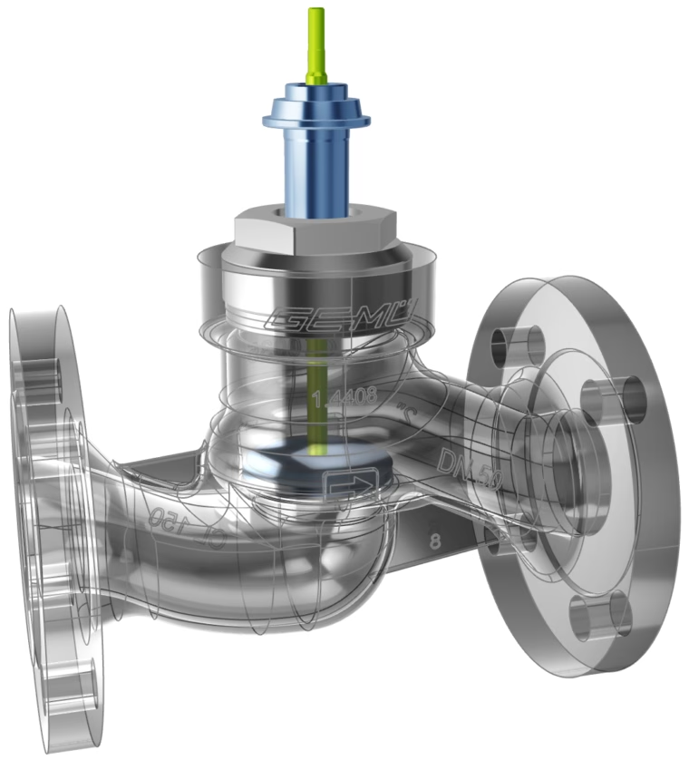
As a classically shaped globe valve, it exhibits sharp changes in the direction of the flow, which create a potential for optimization by reducing the pressure loss in the valve. Within previous investigations, GEMÜ had experienced issues with other CAD tools related to the robustness of geometry variation. This had prevented the exploration of any larger design spaces and motivated the use of CAESES as a dedicated tool for flexible and robust geometry variation.
The specific goal of the investigation was to maximize the so-called flow coefficient Kv, which quantifies the flow rate through a valve at a prescribed pressure drop of 1 bar across the valve.
Geometry Variation Setup
The geometry of the valve was provided by GEMÜ in STEP format and imported into CAESES for parametric remodeling. More specifically, the geometry to be remodeled was the internal fluid volume of the valve, which was extracted from the imported data.
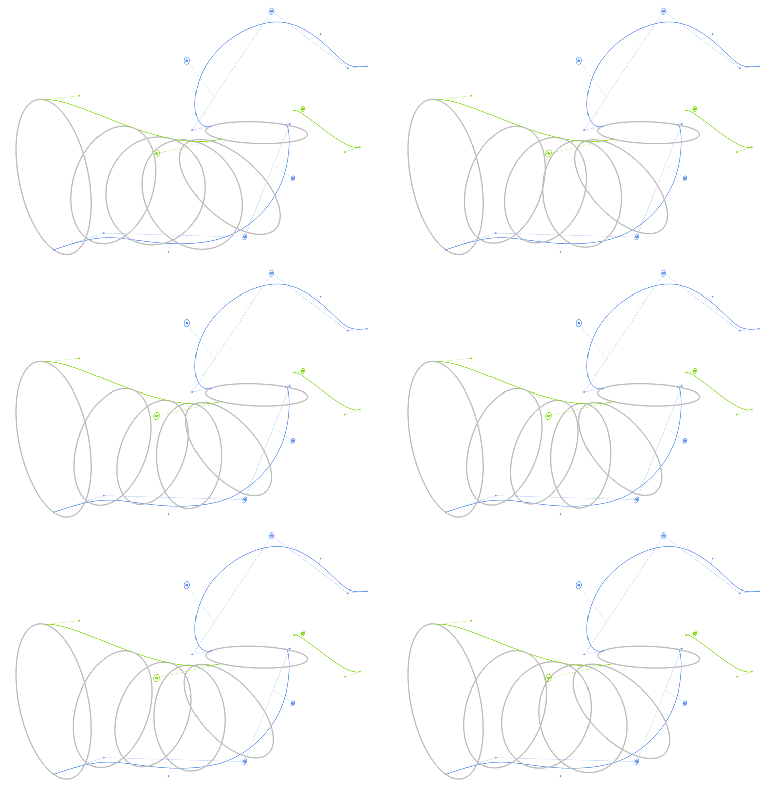
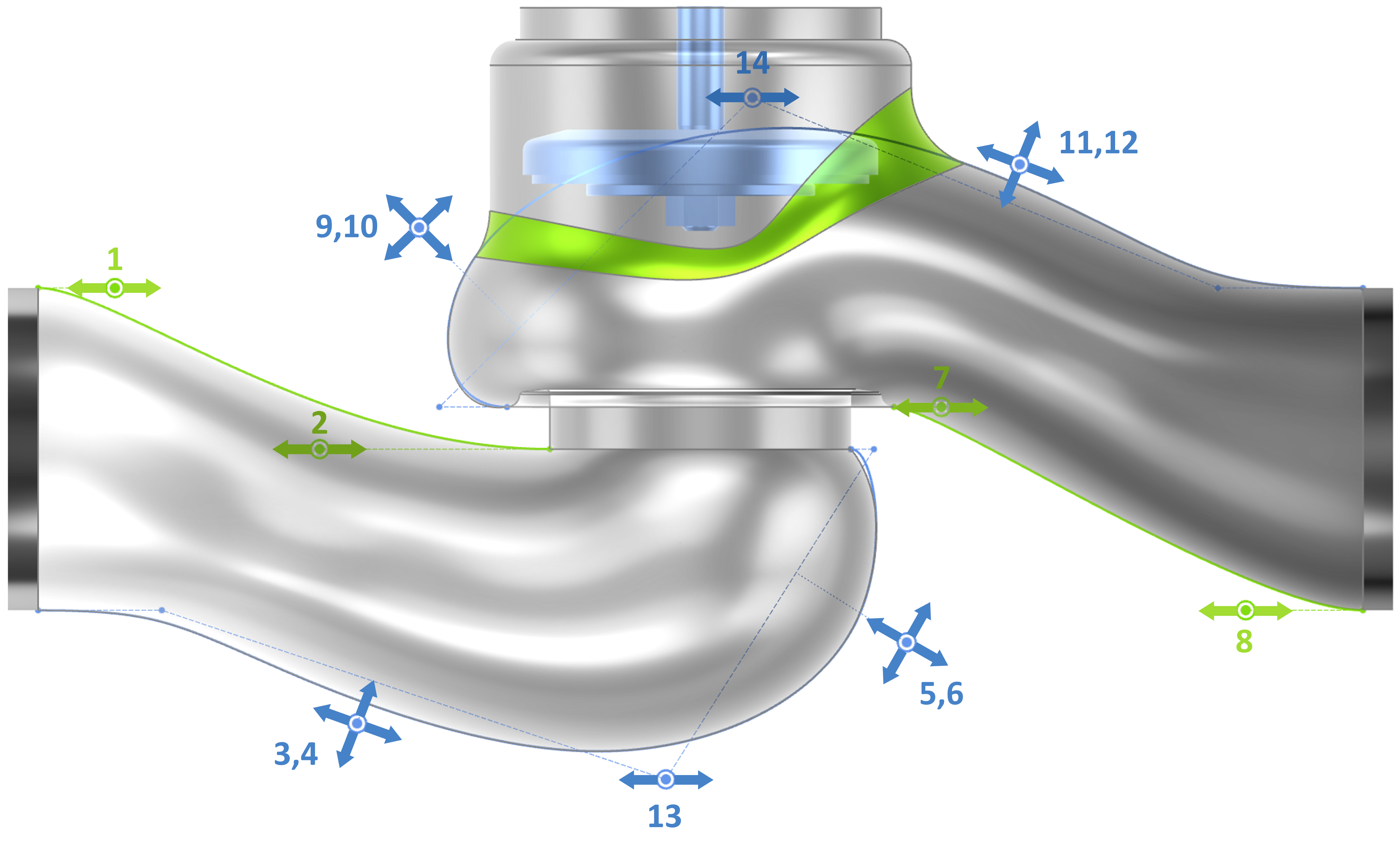
This fluid volume primarily consists of an inlet and an outlet passage, which are separated by the seat onto which the plug closes. The shape of each passage was modeled with two contours, which shall be designated as the short and long contour (in green and blue in the picture below, respectively). Their shape can be controlled by 2 parameters for each of the short contours and 5 parameters for the long contours.
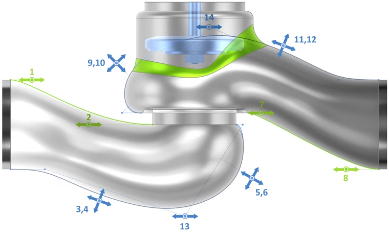
Passage contours with numbered shape parameters
The cross-sections were generated by creating a point on each the short and long contour. These points were connected by an ellipse. The length of the vertical axis is a result of the distance of the two points, while the length of the horizontal axis is defined relative to the vertical axis by an aspect ratio parameter, which is prescribed as a function along the path of the passage. The shape of this function, and therefore the width distribution of the passage, are controlled by two parameters for each the inlet and outlet passage (parameters 15 to 18). In addition, two more parameters allow for a variation of the sweeping speed of the cross-section along the long contour (parameters 19 and 20).
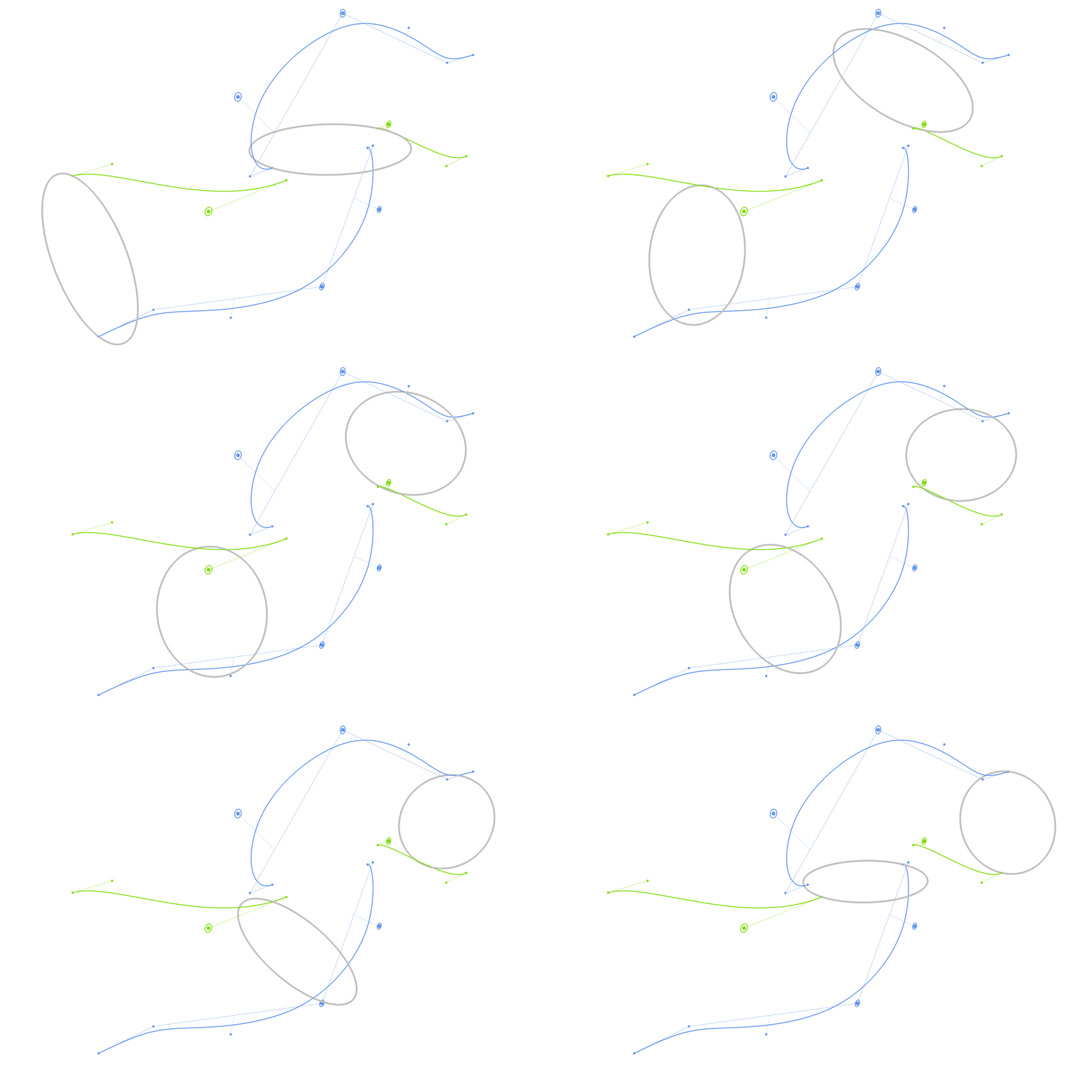
Cross-section sweep along contours for surface generation
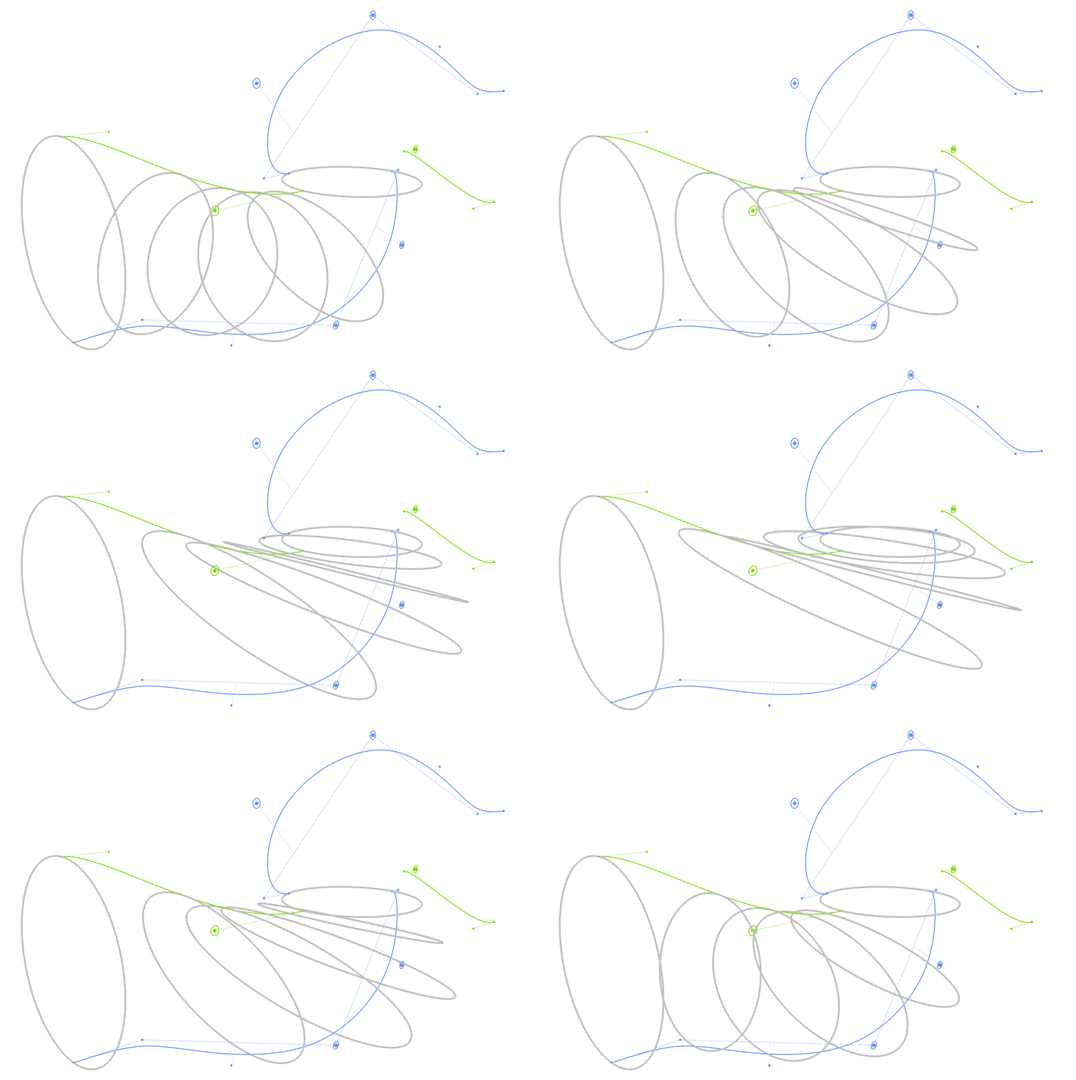
After the generation of the parametric passages, the geometry was completed by the missing parts, such as the seat, plug, and bonnet (partially from imported elements). For purposes of the CFD setup, inlet and outlet were extended in up and downstream direction.

CFD Domain
CFD Automation
The CFD integration in this optimization workflow was somewhat special. CAESES is a desktop application, so typically, CAESES users connect to an on-premise CFD solver running on their local workstation or on an in-house HPC cluster. SimScale, however, is an engineering simulation platform “in the cloud”, so a direct connection between the local machine and the cloud environment had to be established. This was made possible by SimScale’s newly provided API that allows third-party applications to set up cases, run jobs, and retrieve results without manual interaction in the browser-based workbench – a prerequisite for being able to run automated optimization studies.
The communication with SimScale’s API happens through a Python script that contains all the necessary commands to upload the CAD data, import it into SimScale, set up the case, run it, write the result files, and send them back to the local machine.
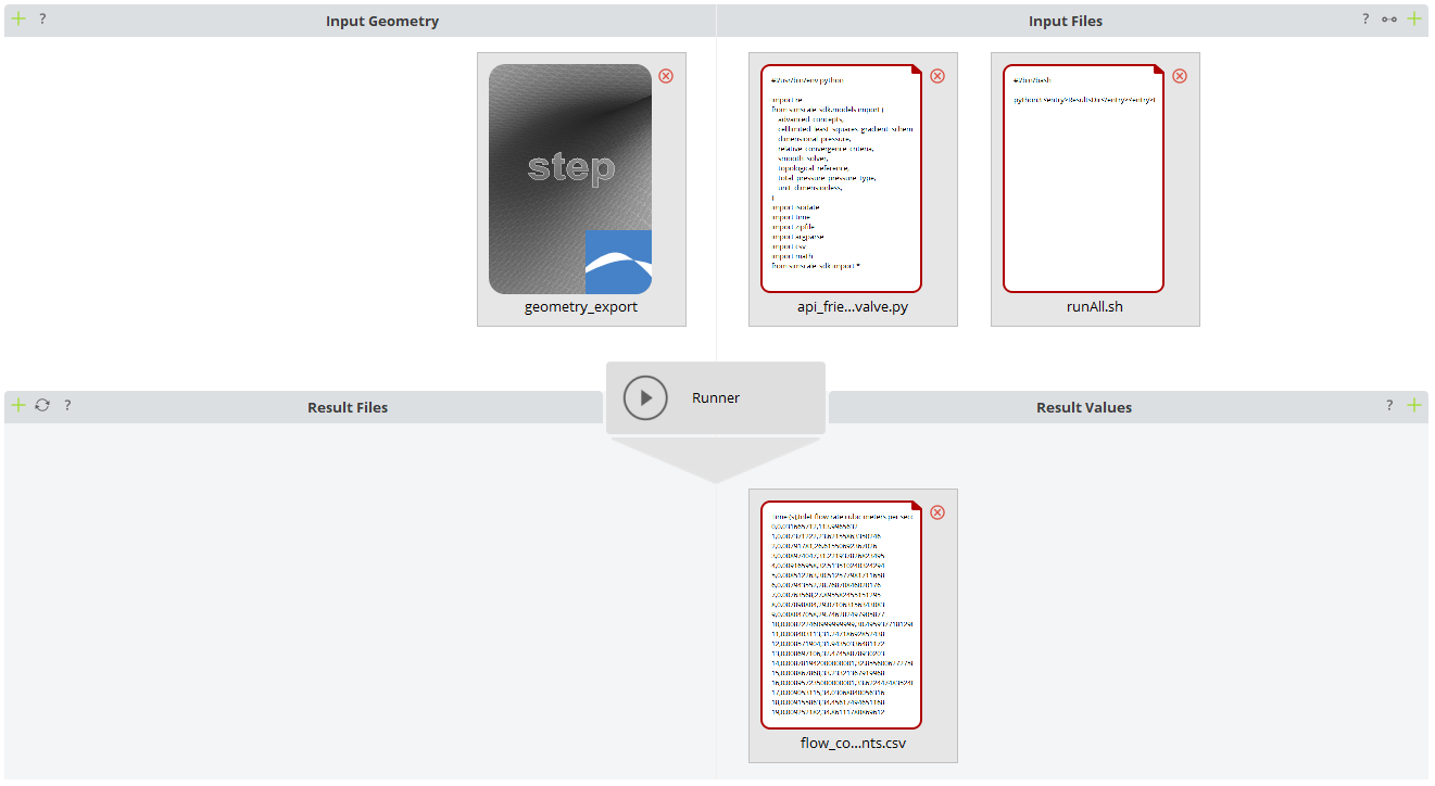
On the CAESES side, the connection to SimScale was accomplished through the usual mechanism, namely CAESES’ Software Connector interface. The input files generated by CAESES for each variant are a STEP export of the geometry, the aforementioned Python script, and a shell script that executes it. A CSV file with the flow coefficients is imported after the computation and parsed for the required results that are used within the optimization process.
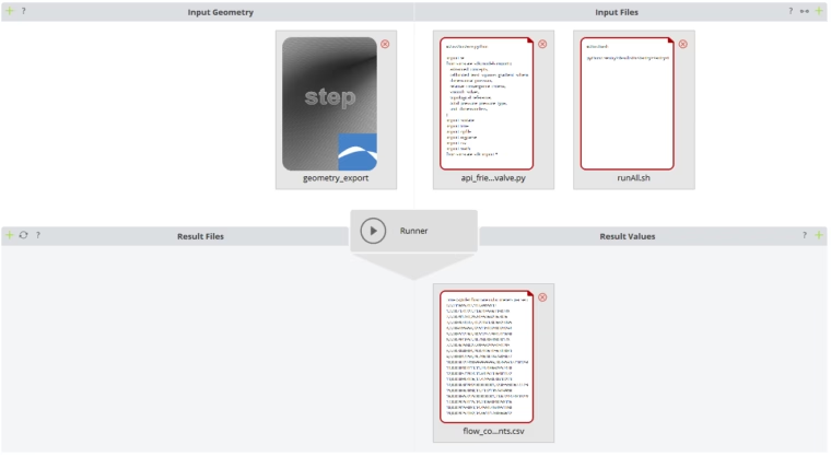
CAESES’ Software Connector for the SimScale connection
As a first test of the connection, an automated valve curve was run, which consists of computing the flow coefficient for a series of plug lift positions, from fully closed to fully open.
Optimization Process and Results
The optimization process was run in several phases. The first campaign included a total of 16 parameters: the first 12 contour shape parameters, and the 4 parameters related to the aspect ratio distribution (15 to 18, see above). It started with a Design-of-Experiments (DoE) encompassing 150 design variants, to broadly scan the available design space. The database obtained from this DoE was used to generate the surrogate model (response surface) utilized by the following optimization process. During this surrogate-based optimization, another 50 design variants were iteratively computed by CFD to check the prediction from the surrogate and augment its precision.
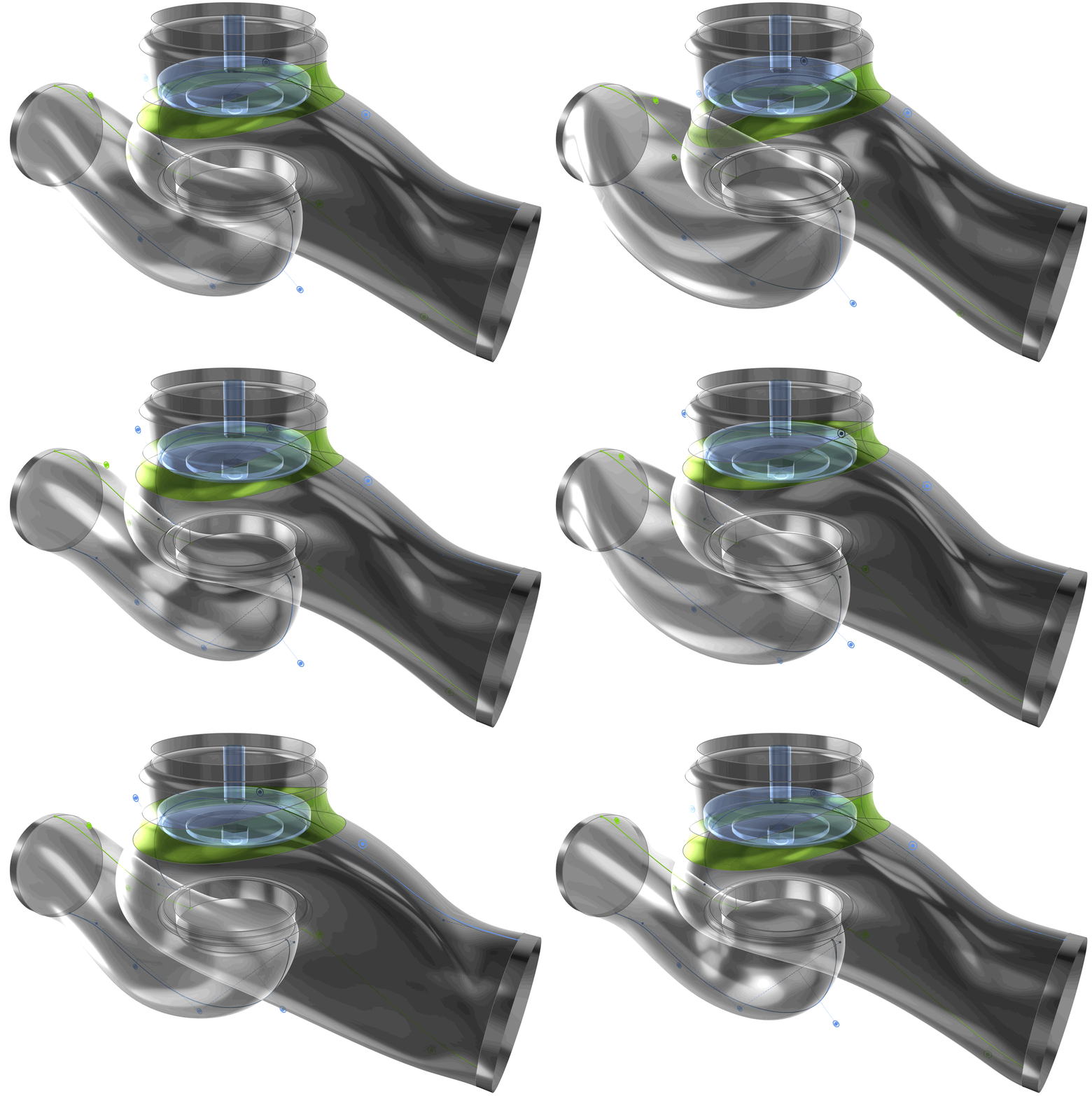
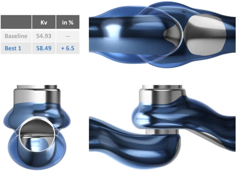
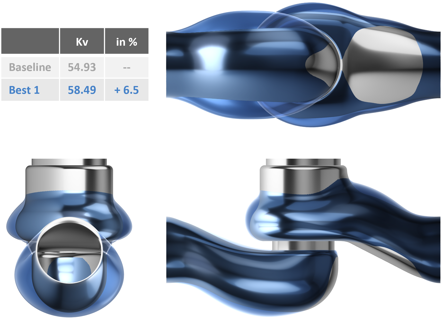
The result from the first optimization yielded an improvement of Kv of 6.5%. It can generally be said that the resulting geometry exhibits a more bulgy shape in both the inlet and outlet passage, which might give the flow more space to smoothly develop when crossing the gap between seat and plug.
For the second optimization phase, with the aim of squeezing out a bit more performance, 8 of the parameters from the first optimization were retained. These were the parameters that proved to have the most influence on the objective function. In addition, two more contour parameters were added (13 and 14), as well as the two sweeping speed parameters (19 and 20, see above). The second optimization was directly run as surrogate-based optimization with a total of 160 design variants computed. In this case, the optimization algorithm creates the initial database by itself and then iteratively refines it with additional computations, as before. This run was followed up with a final small local optimization using only the two sweeping speed parameters.
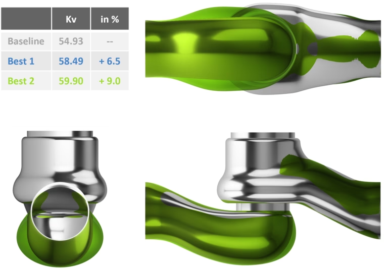
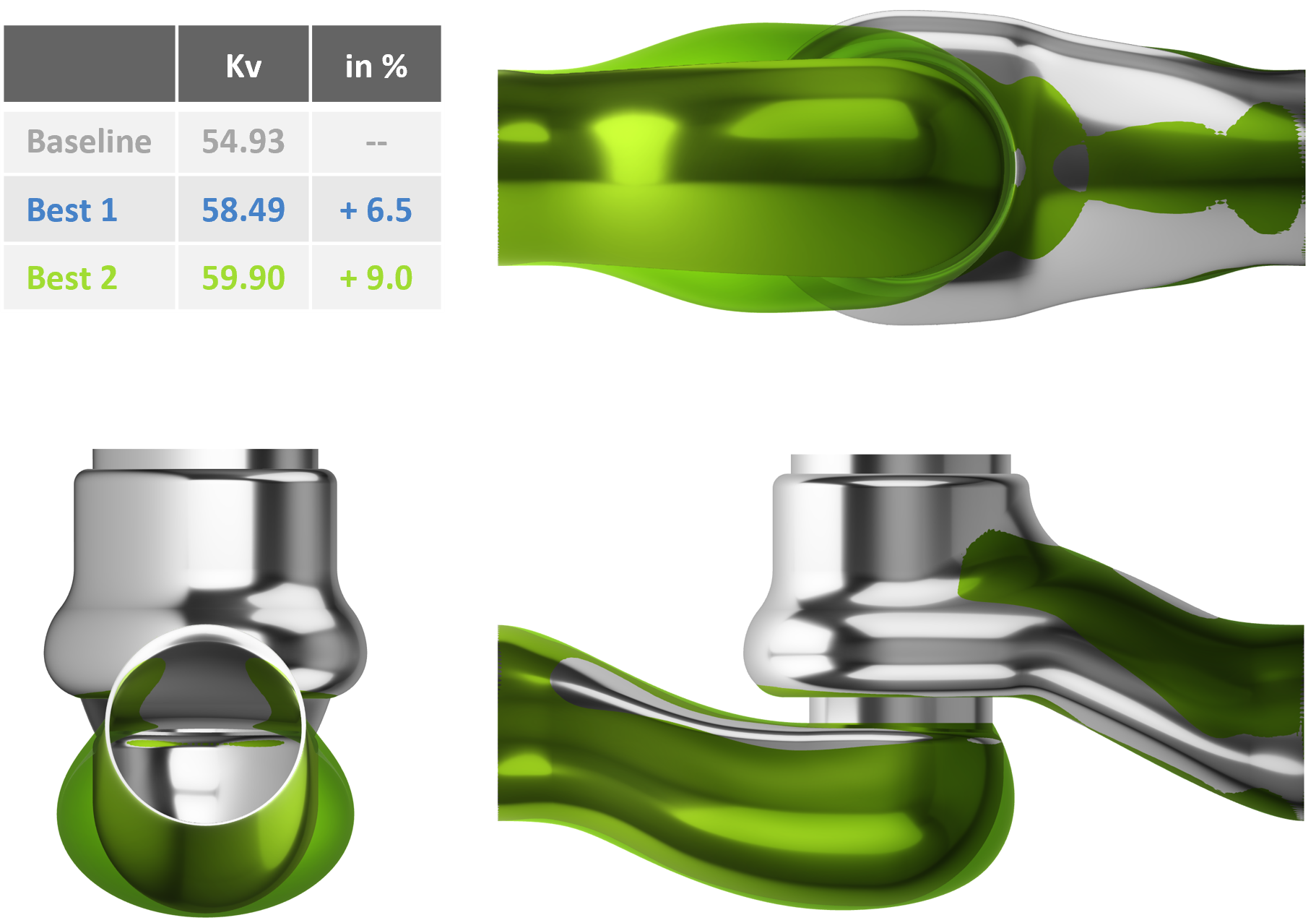
The final optimized design could further improve on Kv, reaching a total improvement of 9%. While the shape of the (lower) inlet passaged had similar characteristics as the previous optimized design, the outlet passage showed an opposite development, by being more slender than the baseline.

This application case was therefore successfully concluded, reaching all set goals: SimScale could successfully be integrated in an automated optimization process as a cloud-based solution, being able to readily provide substantial computing power when only limited capabilities are locally available, and the valve design could be improved by significantly raising the flow coefficient.

Using CAESES and SimScale enables us to perform CFD-driven shape optimizations in a disruptive new way. Due to the high flexibility of the created parametric models, we are developing new, highly efficient valve designs in a much shorter period of time.
Marco Wissinger
Pre-Development Engineer
More Information
Watch the webinar recording about this case study here.
See this overview for the possibilities and capabilities that CAESES offers for valve design.