How to Create a Volute in 10 Steps
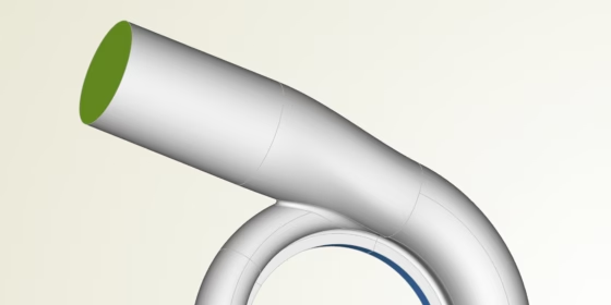
Volute geometries are tricky. They look simple, and designing a single baseline design is not that hard. However, once you are getting into the field of simulation-driven shape optimization, things start to get really challenging. New design candidates need to be generated automatically within an optimization loop, where the geometries are meshed automatically, too. So, in this scenario, you have to make sure that all volute candidates are clean and watertight. In addition, surface patches need to be uniquely identified for the meshing process, and your geometries have to fulfill constraints such as prescribed cross-sectional area progressions and packaging constraints.
In this blog post, we have compiled the 10 major steps we typically got through to create parametric models of volutes in CAESES. In some specific situations and with very specific cross sections, we need to use different approaches. But generally the following steps work well. All screenshots and animations are taken from within the CAESES GUI. Hope you’ll like it!
Step 1: Cross Section Parameterization
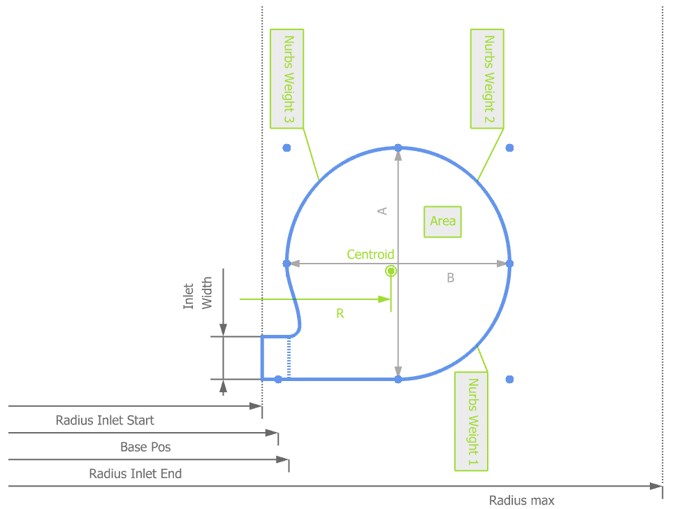
Every company has its own way of describing cross sections. For efficient variation of the shape, you usually need to define 2D parameters such as inlet/outlet size, centroid values, A/R ratos, as well as further geometric controls to fine-tune your shape. These controls can vary a lot, depending on the individual shape you want to achieve. In the picture below, there are NURBS control point weightings that additionally change the shape of the section:
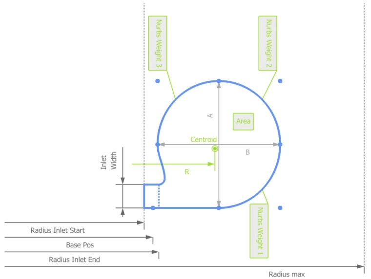
Define a parametric cross section
Step 2: Parameter Distributions
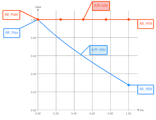
For each 2D parameter of your cross section you can create functions that describe how the parameters behave in circumferential direction. These functions (i.e. parameter distributions) are the ones that will be varied later on during design studies and shape optimization.
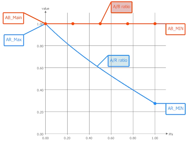
For each parameter, define a flexible function graph
Step 3: Generate Scroll Surface
Based on the cross section definition and the corresponding parameter distributions, you are ready to generate the main scroll surface. In CAESES, we use either a lofted surface for this (to interpolate a finite set of cross sections), or meta surface technology, which directly takes the 2D definitions and function graphs to generate a smooth surface.

Creation of the scroll surface
Step 4: Create Inlet/Outlet
Depending on whether you are designing a turbine or a compressor volute, you need to create the inlet or outlet geometry, respectively. Typically, this is not a big deal and often just a ruled surface or a rather simple B‑spline geometry with a circular connection. Of course, even if this geometry is not that complex, we introduce a couple of shape parameters that let us control the shape, if needed.
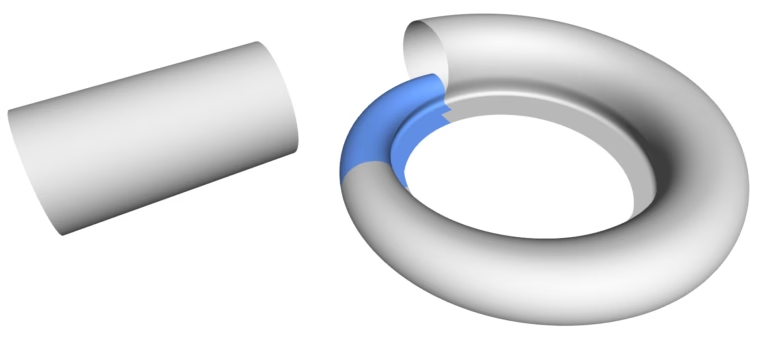
Modeling of the inlet (or outlet) geometry
Step 5: The Smooth Transition
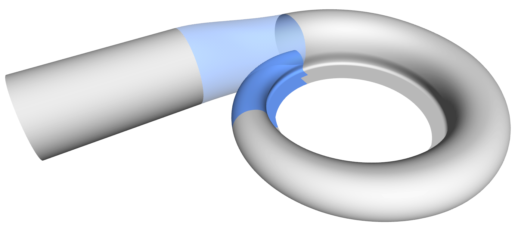
This is an interesting geometry part: The transition from the main scroll to the inlet/outlet geometry. In CAESES, we use either the fillet surface type for this which runs from one surface to another, and which has some controls about the tangential influence. That’s often sufficient and very effective. Or, we again use a meta surface which gives us more detailed control in terms of shape variations.
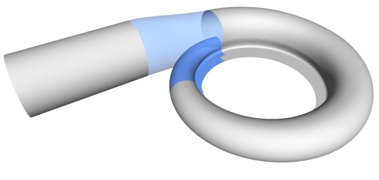
Create a smooth transition with a few design controls
Step 6: Offset Surfaces for the Intersection
So far, this is not that complicated, and one can probably create everything within a few minutes. However, now we have to prepare the intersection process. As a first thing, we create two offset surfaces that will intersect with the initial surfaces.
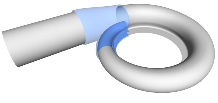
Create offset surface for the upcoming intersection
Step 7: Intersection
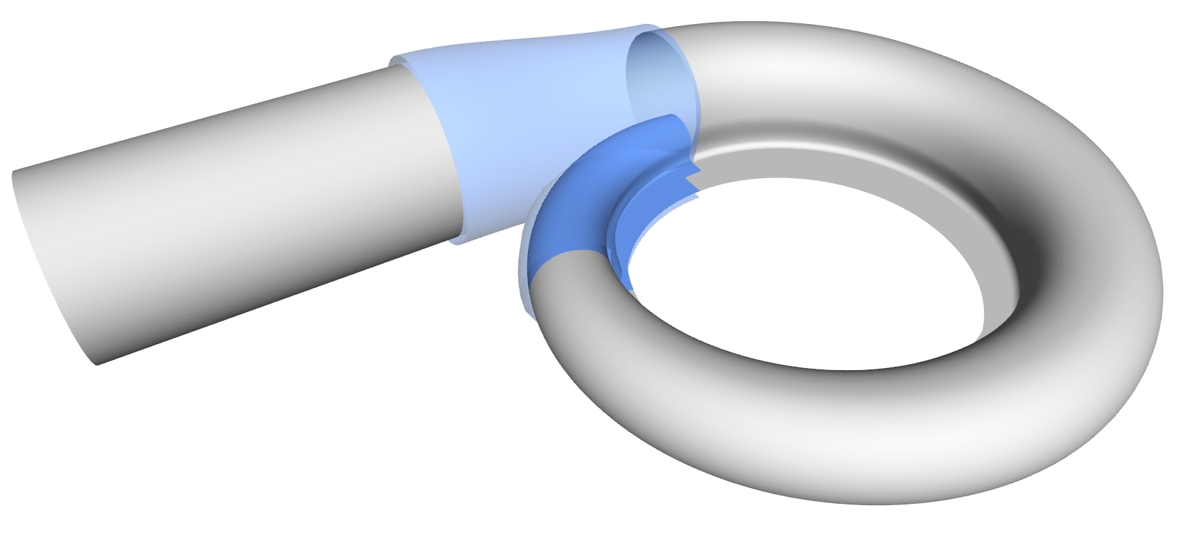
Now we need space for the tongue surface. The initial surfaces are intersected and trimmed with the offset surfaces so that a gap is created. We use either the CAESES’ subsurfaces to represent the remaining parts (modeling in the UV-space of the NURBS geometries gives us some more controls for complex volutes), or simply BReps which handle the trimming part automatically. The latter is shown below:
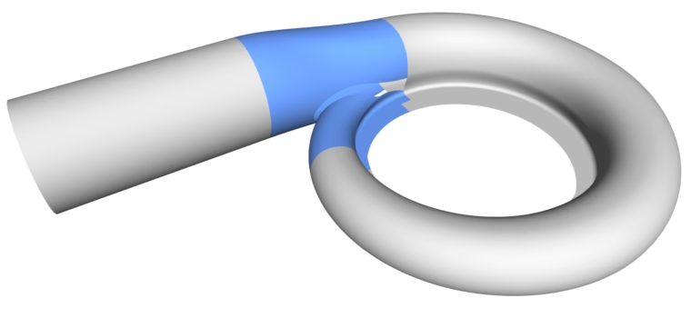
Intersected surfaces that create space for the tongue
Step 8: Tongue Surface
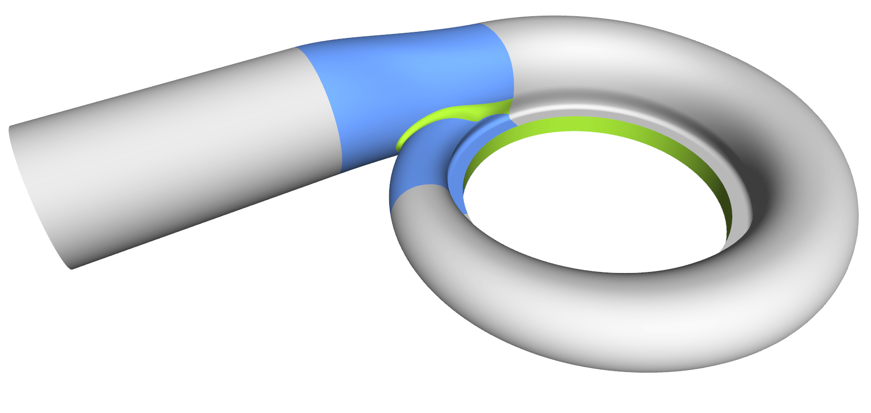
Generating the tongue surface is the most interesting part of the volute design process, and it took us a while to come up with a collection for all sorts of volutes. In CAESES, we mostly use a meta surface or a lofted surfaces with derivative information and rail curves to create smooth surfaces. You typically also want to have control while sweeping the surface, so similar to the volute cross section you can define your tongue cross section as a parametric template. As a result, you have separate parameter distributions for a detailed control of the tongue shape. Some volutes have a constant-radius fillet. In theses cases we simply use the BRep’s filleting capabilities, where you can directly set a radius value during the intersection process.
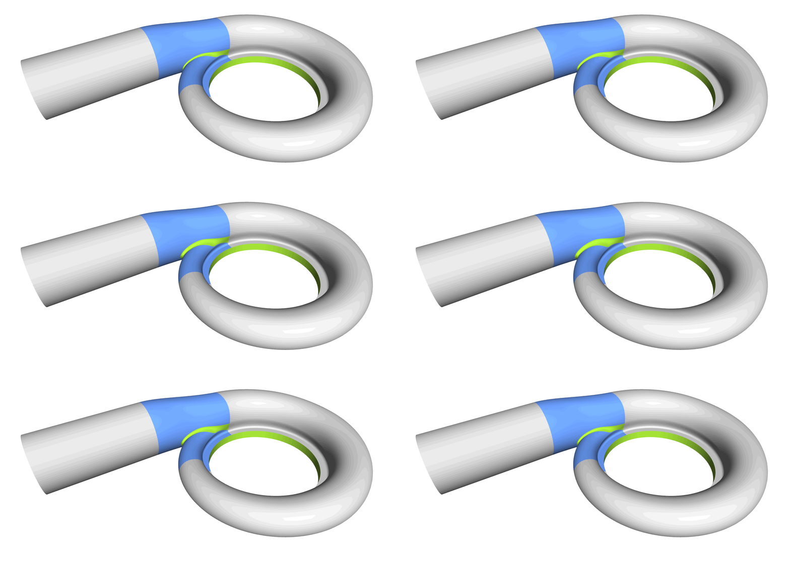
Tongue surface in between of the two other geometries
Step 9: Close Geometry
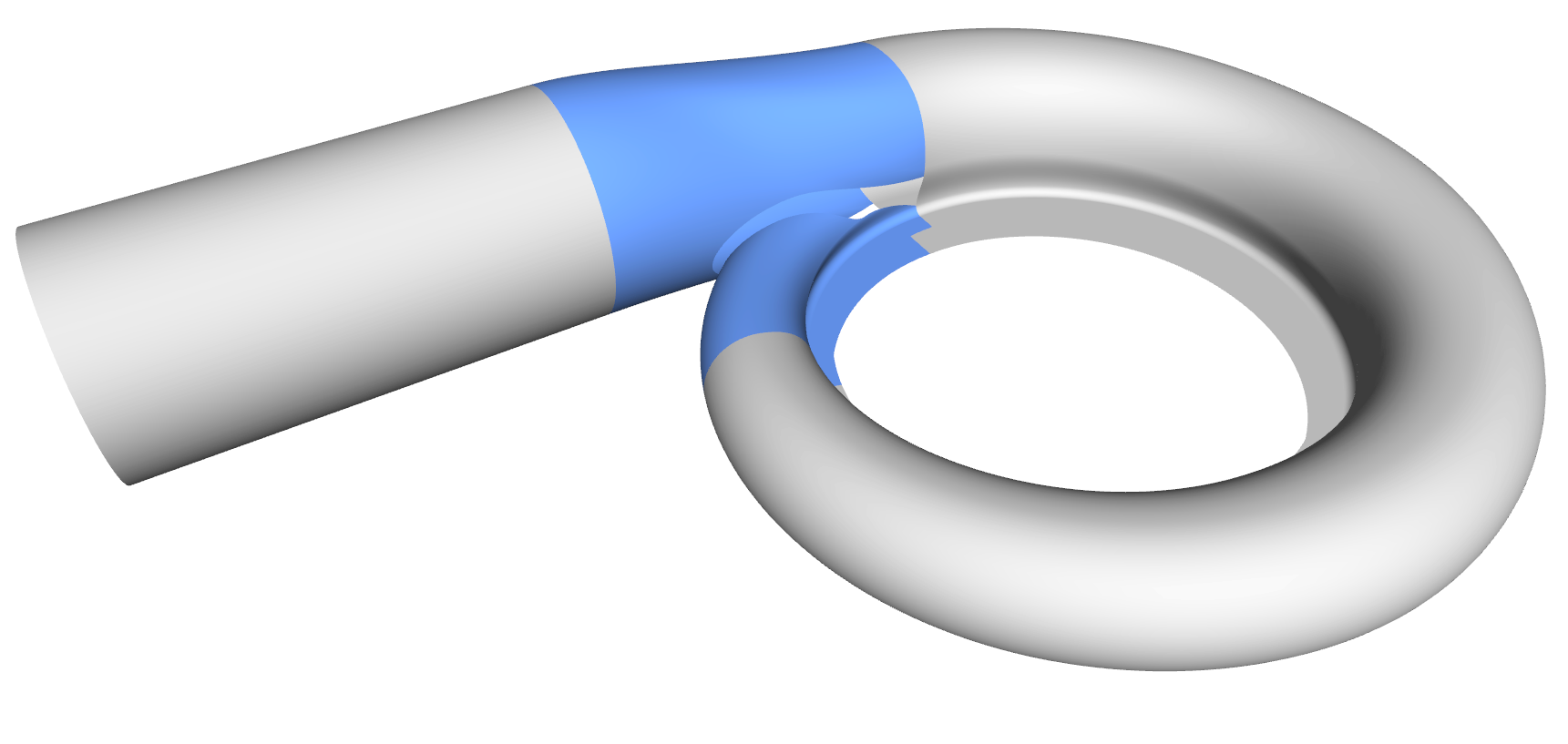
The inlet and outlet needs to be closed with “lids”, so that the entire geometry is watertight. In addition, we can assign colors and IDs to the different surface patches for identifying them later on in the meshing process.
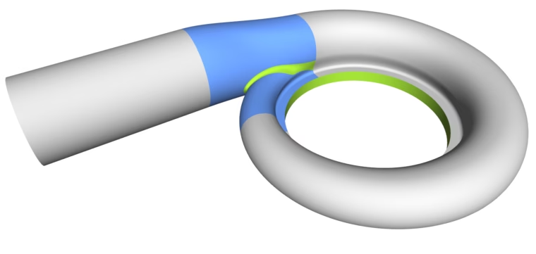
Close all open parts to receive a watertight geometry
Step 10: Check Robustness
As mentioned in the introduction, we do not want to create a single design, but rather a model that can be used for design optimization. Hence, we need to check whether this model is robust during variation, i.e., it should not break or fail to regenerate. In CAESES, we can utilize the integrated algorithms for the parameter studies of this automated check.
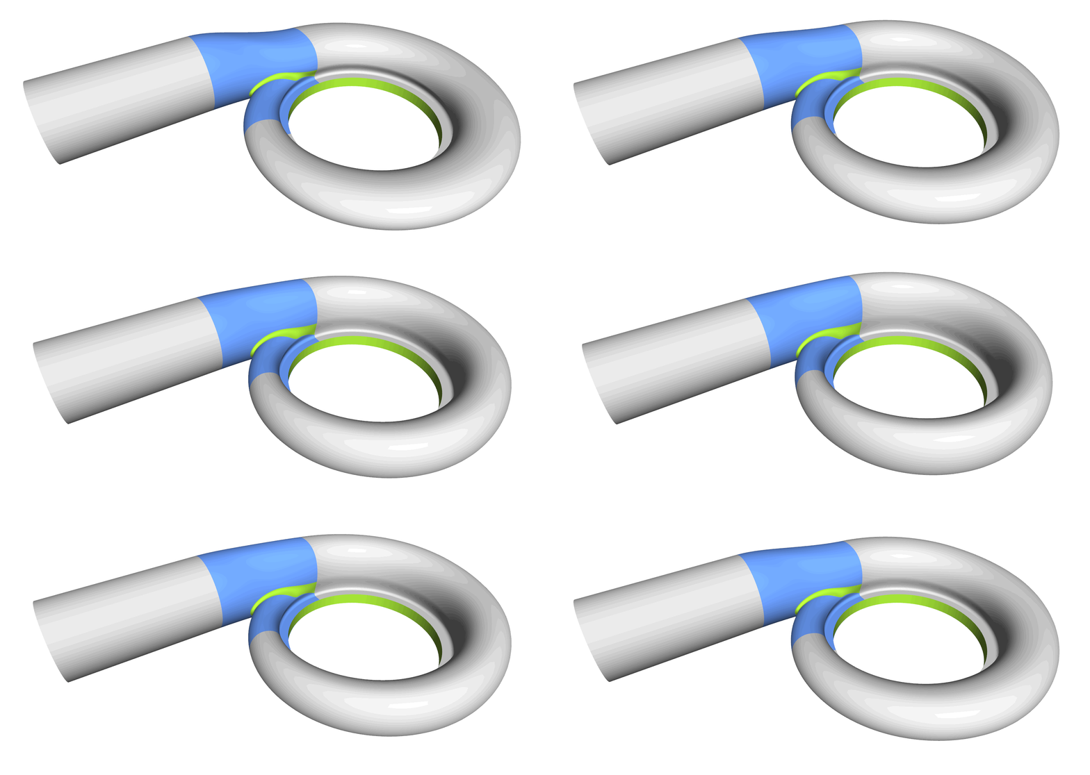
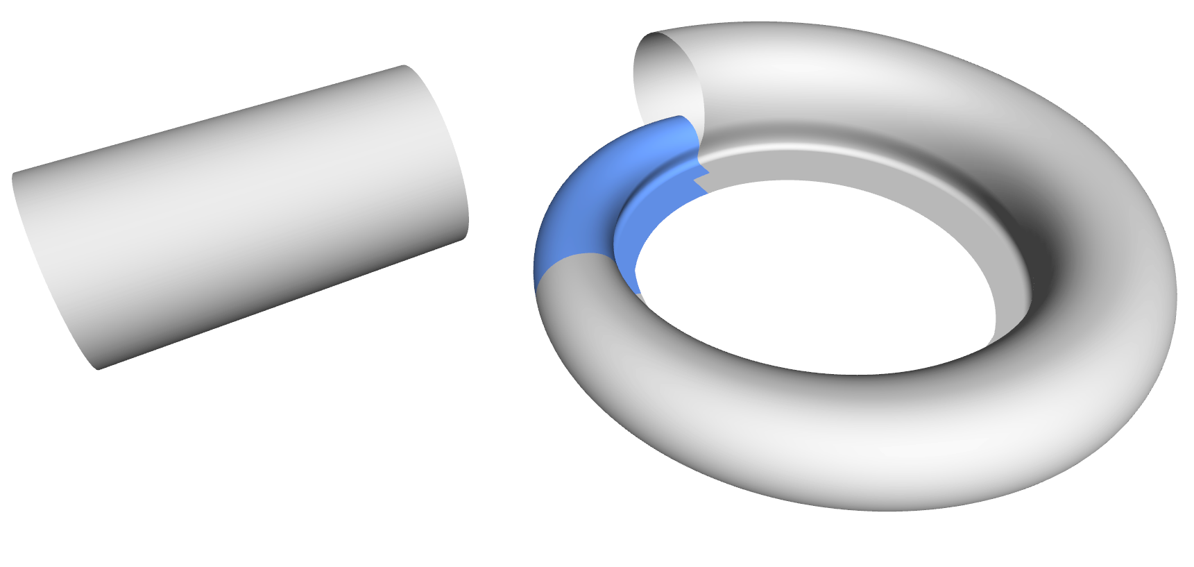
Automated check of the model's robustness using the integrated algorithms for parameter studies
More Information
How do you design variable volute models? What is your experience when it comes to the tongue part? How robust are your models? Let us know your thoughts by commenting below. Feel free to contact us if you have any questions. Finally, see the volute pages for information about the volute design capabilities in CAESES.