Geometry Variation of a Fuel Injector Design
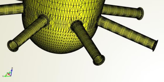
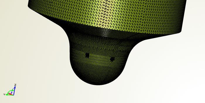
When it comes to the optimization of e.g. diesel engines, we have another interesting component for you: the fuel injector! Basically, this component takes care that the fuel is optimally sprayed into the combustion chamber. This pretty sophisticated product is an impressive engineering and manufacturing master piece (BTW: Everything is really tiny!). We recently needed to come up with a quick method to change the existing nozzle geometry of a fuel injector. The geometry was imported into CAESES®, using the STL format. The following screenshot shows a slightly changed design of what we had worked on:
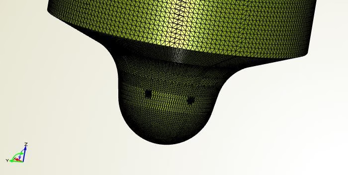
Typical injector geometry
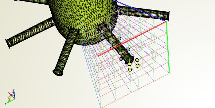
CAESES® offers the possibility to apply so-called free form deformations to existing geometries. So this is what we did: We created a box around one of the nozzles, and defined some expansion strategies. With this, the nozzle could be enlarged and even fully changed in its shape. Sure, there are limitations in terms of manufacturing etc. But at this point in time, we tried to set it up as flexible as possible. Here is a screenshot of the setup where the outer geometry was removed for visualization purposes:
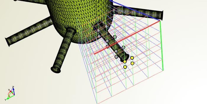
Setup of a free form deformation to modify the nozzle
In a next step, we defined design variables for the expansion factors, to make it ready for automated studies. The following animation shows the deformation box and the effect on the geometry:
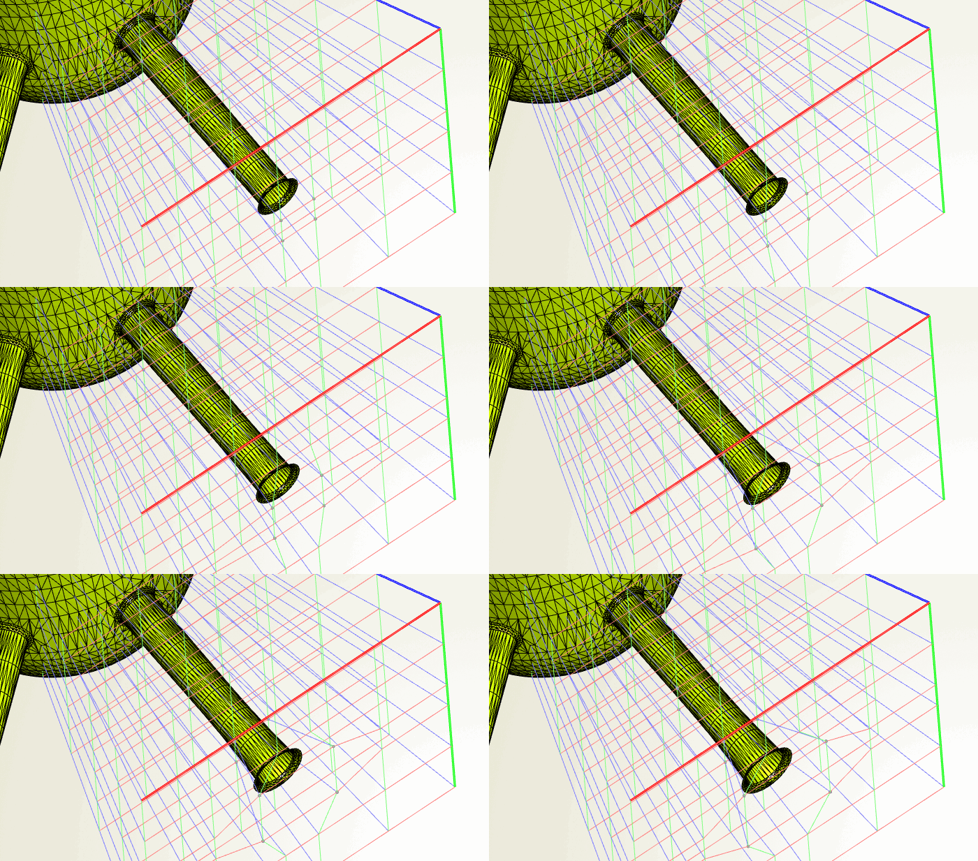
Change of the deformation box to apply shape changes
When we finished this setup for the nozzle, we applied it to the other nozzles, i.e. they were changed in the same way. We handed over the entire setup to the engineer who requested this shape changes. Being the expert in this field, he simply continued to fine-tune things a little bit further, according to his technical requirements and constraints. Finally, he run design studies where the entire process was fully automated (geometry changes / meshing / CFD analysis). For illustration purposes, here is a set of animations that show some automated shape changes:
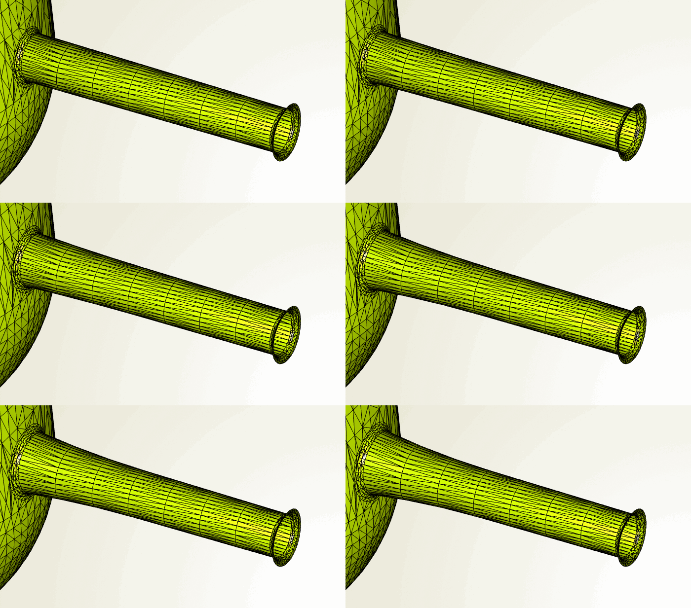
Inner variation
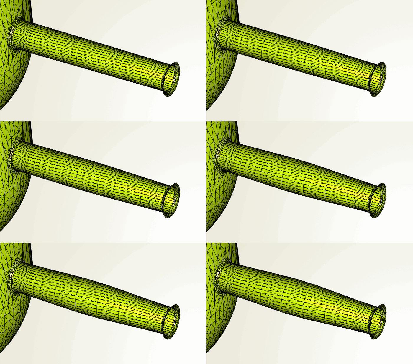
Middle variation
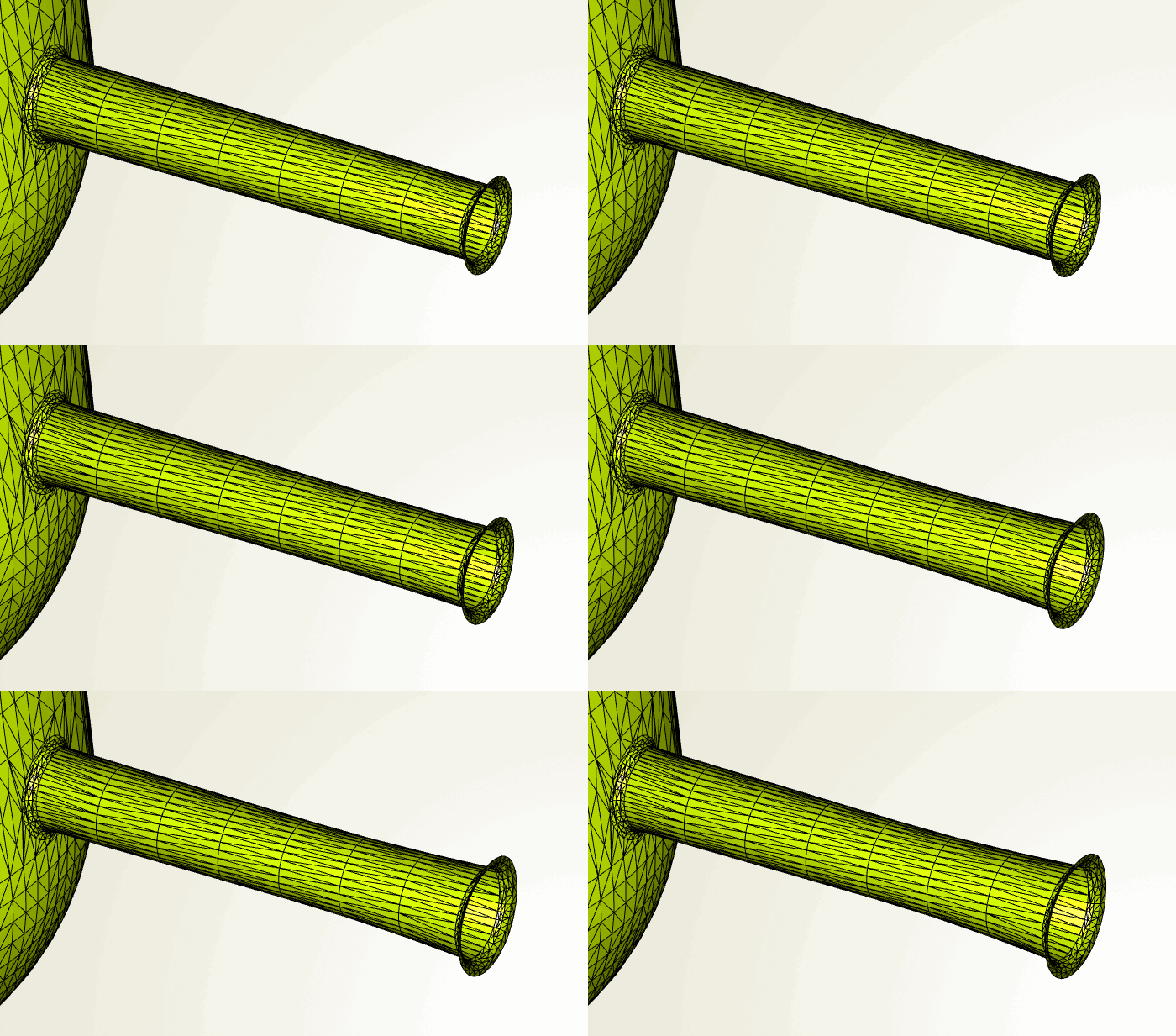
Outer variation
More Information
Free form deformations are part of our pro edition of CAESES®, and it nicely complements the general CAD functionality for CFD engineers. In similar projects, we created a fully-parametric model for injectors (instead of deforming an existing one), which usually gives you even more control, while at the same time the number of variables can be reduced.