Automated Generation of Parametric Propeller Models
In propeller modeling, often a very similar design approach is applied. Typically, the blade is described based on a set of functions for rake, skew, pitch, etc. and a profile section definition. Additional parameters, such as the number of blades and the propeller diameter, are then used to create the final propeller model. In this blog post, we’ll take a quick look into an automated workflow for the fast and flexible design of propeller CAD models that are also suited for automated shape optimization with CFD (Computational Fluid Dynamics). The procedure is entirely automated and can be broken down into the following sub steps:
Create a Propeller Model from Existing Data
If existing propeller data is stored in a standardized manner, such as offset tables at different radii and discrete data for the design functions, a parametric propeller model can be derived automatically in a few steps. For the example and the pictures in this blog post, the Propeller Free Format (PFF) was chosen as an input format. CAESES allows you to load existing propeller geometry that is stored in the PFF format and automatically convert it into a flexible, robust CAD model. If other formats are used in a company, there is the option to use feature definitions for custom import routines.
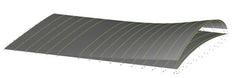
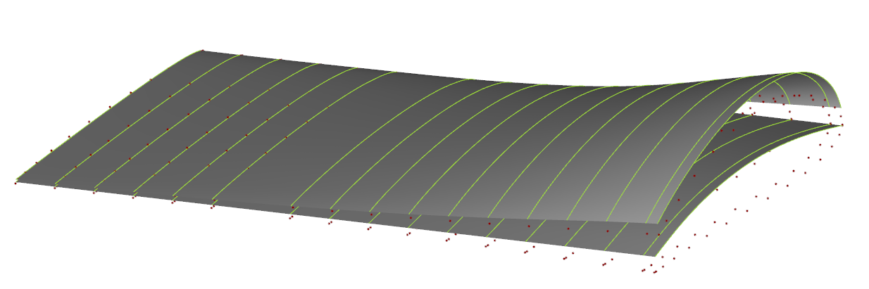
Imported propeller data from an existing PFF file, and the resulting meanline and thickness distributions (interpolated by NURBS surfaces) at normalized chord length
Extracting Camber and Thickness Distributions
Let’s assume we have an imported point cloud of the 2D propeller sections as shown in the previous picture. Preliminary parametric sections are then created as interpolation curves at all given radii. Circles are inscribed into each profile curve to determine both camber and thickness as a function of chord.
Fairing is automatically applied to the camber distribution to ensure a smooth shape especially around the leading and trailing edge region. The resulting camber and thickness distributions are then interpolated by two surfaces, to have a continuous definition with regards to the full propeller radius, i.e, also in between of the single sections.
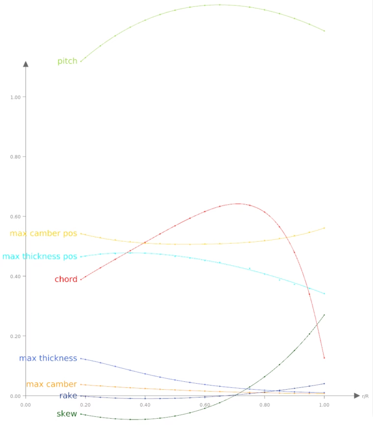
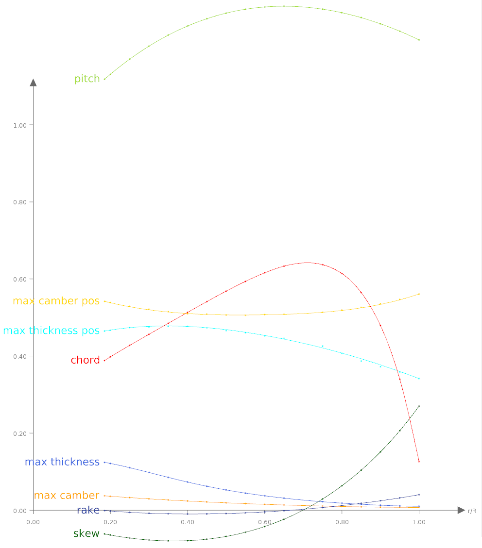
Propeller blade functions, generated from the data
The radial functions for all parameters are interpolated with NURBS curves. Each of the resulting curves is additionally parameterized to allow the designer flexible modifications. If needed, any user defined curve can be used to replace the automatically created function.
3D Propeller Model Generation
For the local section profile, the interpolation surfaces for camber and thickness can be intersected at any radius to provide the local chord-wise distributions. The thickness is offset normal from the camber line, the leading edge region receives an additional fairing and the trailing edge is closed. The chord length, maximum camber position, maximum camber, maximum thickness position and maximum thickness are adjusted according to the design functions.
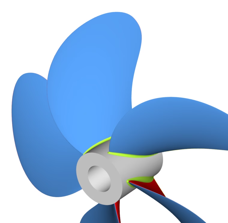
Final parametric propeller model in CAESES
Pitch, rake and skew are taken into account when generating the blade via CAESES’ generic blade functionality. The number of blades, propeller diameter, hub radius and extension can be set to complete the definition.
Variable Radius Fillet
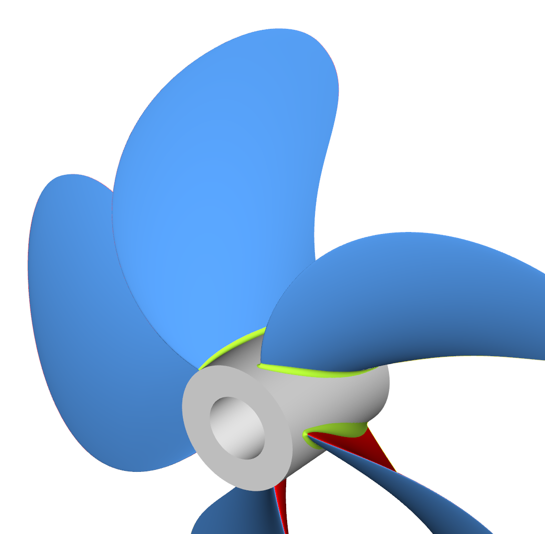
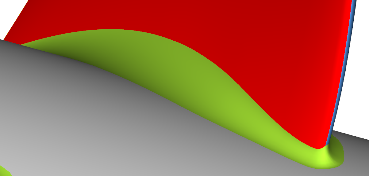
A fillet is created at the blade root with a variable radius. The distribution function might be either fully customized or based on the thickness of the root profile, e.g., 2/3rd and 1/3rd of the profile thickness on the pressure and suction side, respectively.
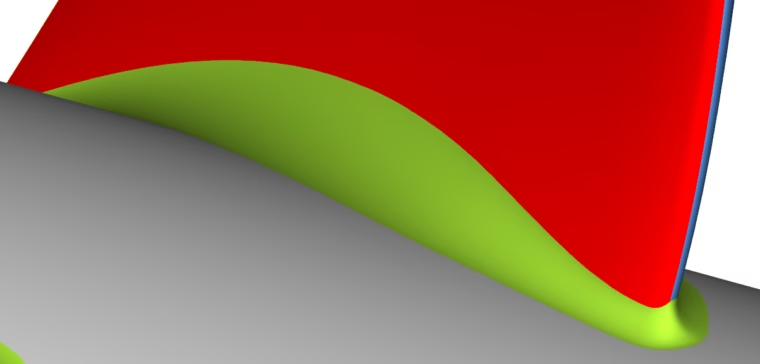
Variable fillets between the hub and the blade
Export Formats
CAESES gives you a set of standard export formats, such as IGES, STEP, STL or Parasolid. For proprietary formats, the scripting environment of CAESES can be used again.
Solid with Boundary Conditions
In case a CFD analysis will be conducted, a solid propeller geometry including a shaft and a closed tip can be created in CAESES with a few clicks. Boundaries and refinement regions are set as needed for the specific CFD code. Finally, a computational domain can be exported, either for the single blade or for the entire propeller.
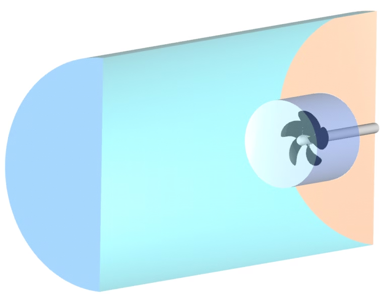
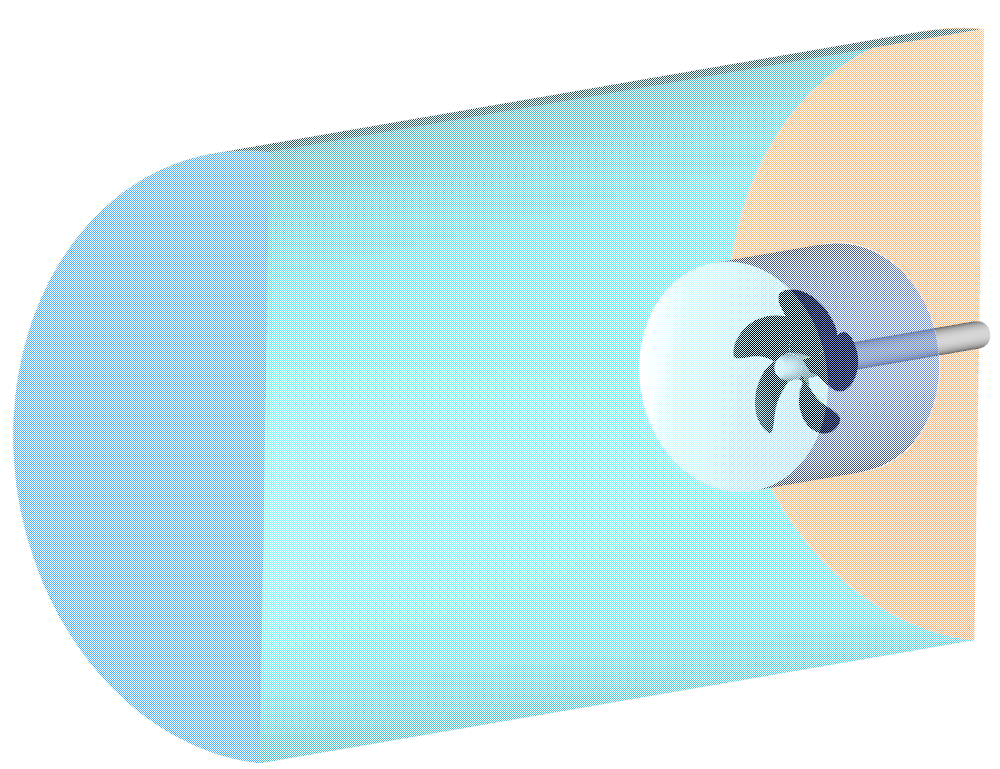
Solid domain for meshing and CFD analysis
More Information
If you would like to learn more about propeller modeling in CAESES, please see the marine section.
Subscribe Newsletter
Did you like this post? Then sign up for our newsletter!