Top 5 CAESES features you might not be using (but should be)
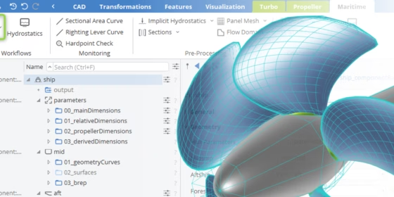
When it comes to simulation-driven design, every minute counts — and so does every feature in your toolset. CAESES is packed with powerful capabilities designed to accelerate your design process, improve performance, and streamline integration with simulation tools. But with so many options available, it’s easy to overlook some of the more advanced or specialized features.
In this blog, we highlight five standout features in CAESES that often fly under the radar but can make a big impact when put to use. Whether you’re working on hull optimization, propeller design, or any complex geometry task, these tools can help you take your design automation to the next level.
1. Generic Curve: Flexible 3D Curve Modeling with Full Parameterization Control
Few tools in CAESES offer as much flexibility and control as the Generic Curve. It’s one of those features that feels almost limitless once you start exploring it. At its core, the Generic Curve lets you describe geometry mathematically — with x(t), y(t), and z(t) defined as functions of a single parameter t that runs from 0 to 1. From simple mathematical functions such as sine or helical definitions used in engineering tasks to advanced modeling challenges like blending between shapes or controlling internal parametrizations, you can turn pure mathematics into geometry with elegant precision. There’s a bit of a learning curve (no pun intended), but once you’ve mastered it, you’ll find it’s one of the most powerful and expressive tools in your design toolkit.
In real-world design, the perfect shape is rarely known in advance — it often lies hidden somewhere between known extremes. The challenge is to explore that space freely while staying true to physical, functional, or manufacturing constraints. The Generic Curve enables exactly that: it provides the control needed to preserve design intent while still allowing maximum geometric variation. You can morph between existing geometries, interpolate between imported and designed curves, or define entirely new transitions — all while keeping your model robust and responsive. This makes the Generic Curve a powerful enabler for discovering untapped potential within your design space, where optimization meets creativity and precision.
For anyone who loves experimenting with geometry and pushing beyond traditional CAD boundaries, the Generic Curve is a true hidden gem. It embodies what CAESES does best: turning engineering ideas into real, functional design freedom and optimization potential.
2. Nested Geometric Optimization: Enforce Geometry Constraints While You Optimize
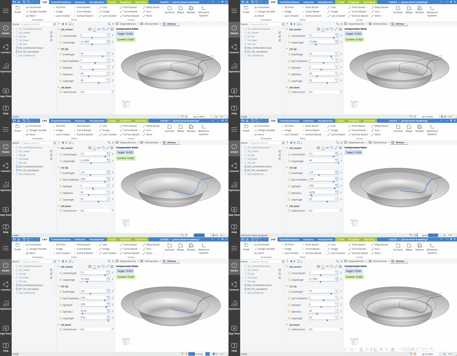
In many design processes, optimization entails running simulations, generating design variants, and hoping that the outcome will meet all given requirements and constraints. With CAESES, that optimization process can be made smarter. Using nested geometric optimization, you can enforce geometric constraints (cross-sectional area, for example, compression ratio, or displacement) directly inside of the main optimization loop — automatically and exactly.
This guarantees that every variant you create is not only parameterized but also valid by design. A piston bowl will always meet the exact compression ratio you specified. Each volute cross-section will fit exactly to your specified area progression. And any ship hull that you send to CFD will already have the correct displacement. All of which saves you time, reduces infeasible variants, and ensures valid and quality designs for simulations — every time.
Maintaining key geometric constraints, such as a piston bowl’s compression ratio, can be time consuming and troublesome if performed manually, especially if numerous design variables are interrelated. CAESES’ Design Engines can be used to accomplish this for the user by continuously updating dependent variables to fulfil a given constraint. For example, you want to change one design parameter but keep the compression ratio constant. Using a Design Engine without variant generation in an inner optimization loop keeps your model “up-to-date” with the necessary design requirements, minimizing time and potential errors.
See how this works in a diesel piston bowl optimization case study.
3. Automatic Creation of Feature Definitions: Visual Programming Made Easy
Feature Definitions in CAESES allow engineers to program libraries of reusable custom functions and components, speeding up model setup and standardizing workflows.
The possibility to automatically generate Feature Definitions from objects in the Object Tree could be one of the most user-friendly features in CAESES. You can turn selected geometry into a reusable feature with the press of a button! This is a great feature for engineers wanting to try out the powerful Feature Programming Language (FPL) without writing any code. You can use it to get into visual programming, while getting comfortable with script-fueled ideas, all the while speeding up the modelling process. This creates a way for users with less CAESES experience to knock down the barriers of creating modular, parameterized designs.
4. Data Reduction and Refinement: Fit the NURBS Definition to Your Task
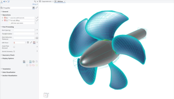
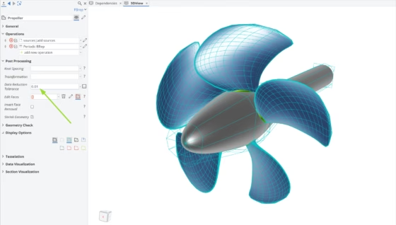
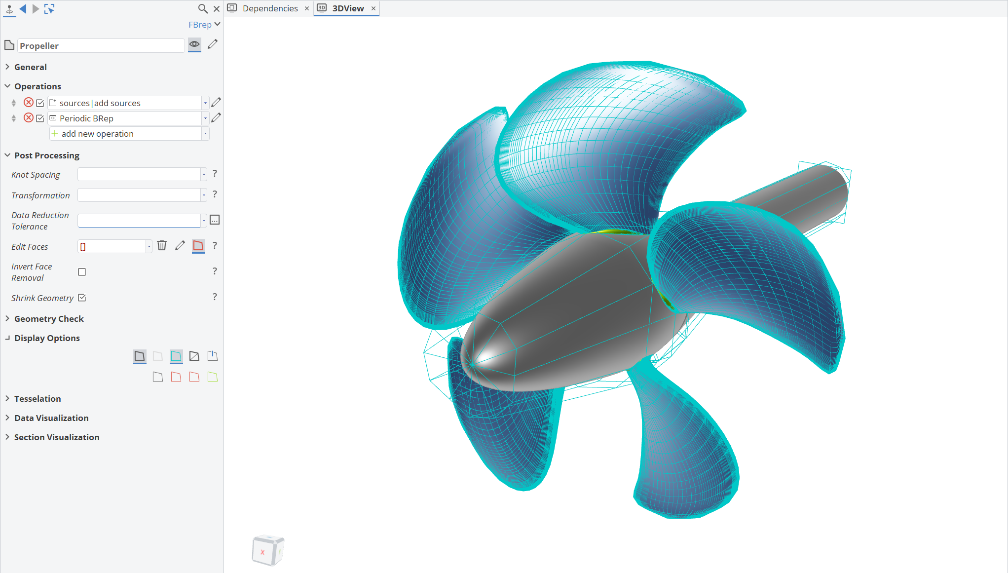
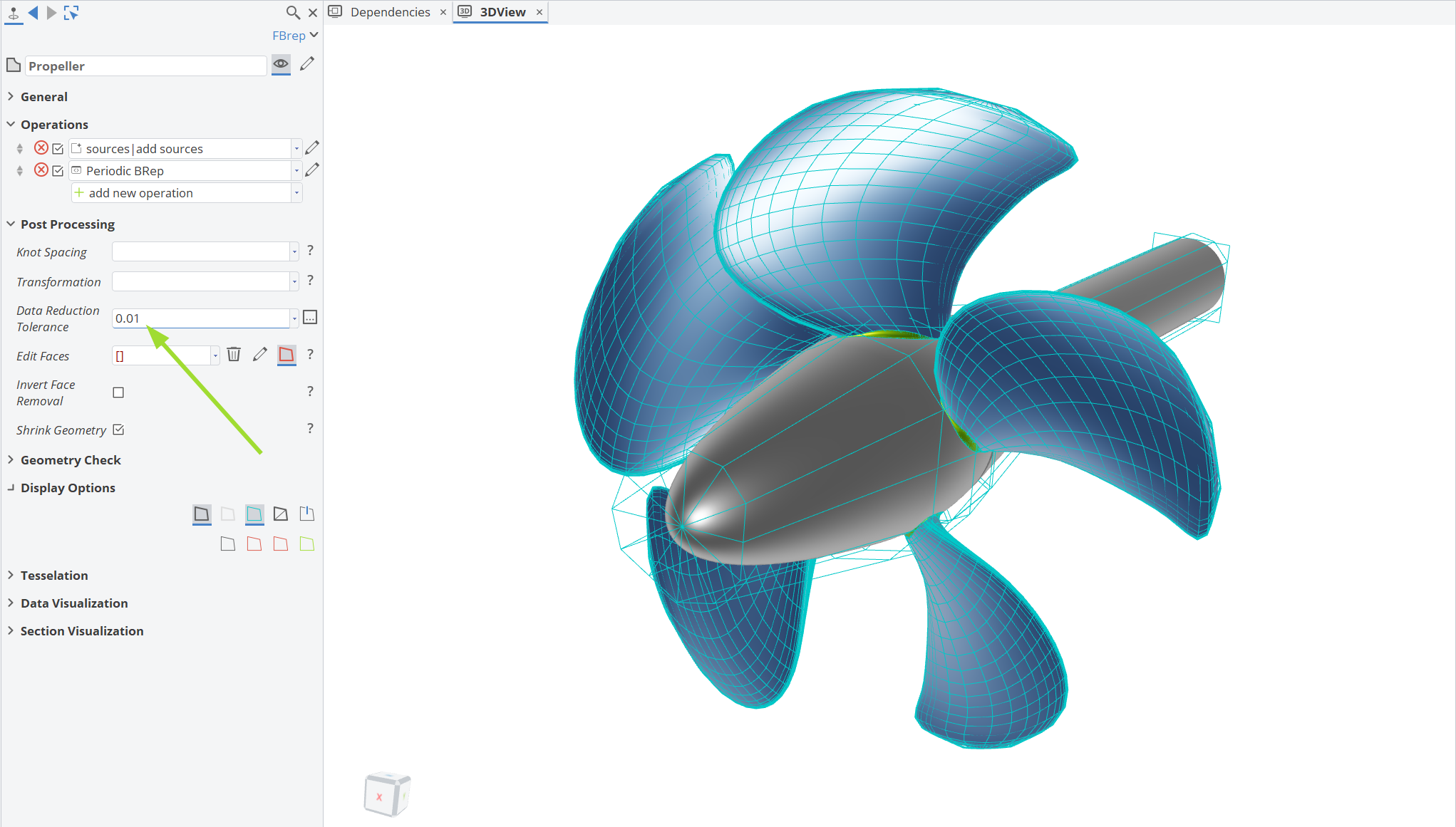
In the Post Processing section of a BRep object, you can find options to reduce or refine the underlying NURBS data. For instance, you can refine your control polygon to have more control vertices available when applying shape deformation techniques in areas that were previously sparsely populated by vertices (deformation to NURBS geometry is applied by shifting the control vertices).
Conversely, you can reduce the amount of data, which for example impacts the file size of the geometry export, but also the processing speed for operations concerning that geometry within CAESES. In this case, vertices are removed from the control polygon according to an absolute accuracy tolerance, i.e., vertices are thinned out until the deviation of the BRep from the original shape reaches the given tolerance.
5. Custom Types and Workflows: Encapsulate Complex Processes into Reusable Building Blocks
With CAESES, you can even define custom types using Feature Definitions. These are not just features, they’re customized building blocks with rich and complete complex functionality. Custom types can reduce complexity by enabling teams to wrap complex engineering processes into reusable features. This promotes collaborative work and simplifies model upkeep, while also speeding up the development loop across multiple projects.
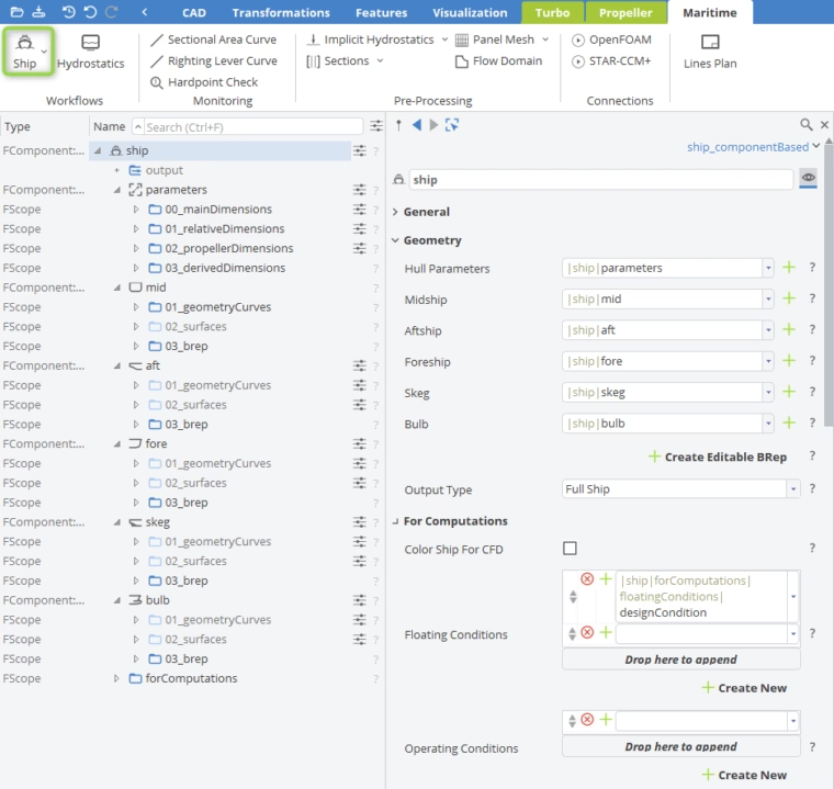
Custom types go hand-in-hand with our recently added and well-adopted workflows. Workflows offer a quick and streamlined method to build fully parametric models for specific geometries (for which the given Workflow has been set up) and walk you through the process in a structured but flexible way.
The amount of time saved once you have a robust base model for a type of ship, turbomachinery, propeller, etc., is immense. With only minimal input, you can build an initial model within the Workflow and then customize it to meet the needs of your project. Workflows are not only limited to the ones provided by CAESES out-of-the-box (for turbomachinery, ship hull, and propeller modeling), but you can also develop your own Workflows implementing new modeling ideas. This provides your team with a custom toolbox, ensuring that you organize know-how and move more quickly in the design process.

Conclusion
Every design project comes with its own challenges — whether it’s meeting strict constraints, managing complex data, or simply finding faster ways to get from concept to simulation. The features highlighted here may not always be top of mind, but they can make a real difference in streamlining your process and unlocking new levels of flexibility.
By taking advantage of tools like Generic Curves, Nested Optimization, automatically generated Feature Definitions, Data Reduction and Enhancement, Custom Types, and Workflows, you can move beyond traditional CAD limitations and accelerate innovation in your workflow.
If you haven’t tried these capabilities yet, consider exploring them in your next project. They might just be the hidden accelerators that help you push your design automation further — and we’re here to support you along the way.