Sensitivity Approach for a Turbopump Inducer Geometry
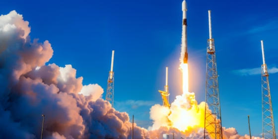
Turbopumps are a crucial component in the design of liquid propellant space launch systems. This type of turbomachinery is used in the feed systems of the rocket engines in order to overcome the combustion chamber pressure and supply the propellants with a sufficient flow rate to achieve high rocket thrust values.
As a result of the current demand for a reduction in total weight, very high rotational speeds, and reduced pressures in propellant storage tanks, accurate design and performance prediction of turbopumps for space applications is required, with the aim of maximizing engine reliability throughout its life cycle. From this point of view, it is essential to include the prediction of the possible initiation of cavitation in the propellant flow within the design process of the turbopump. It is also necessary to evaluate the consequent performance degradation, because this type of turbomachinery frequently works in conditions characterized by fluid-dynamic and rotor-dynamic instability.
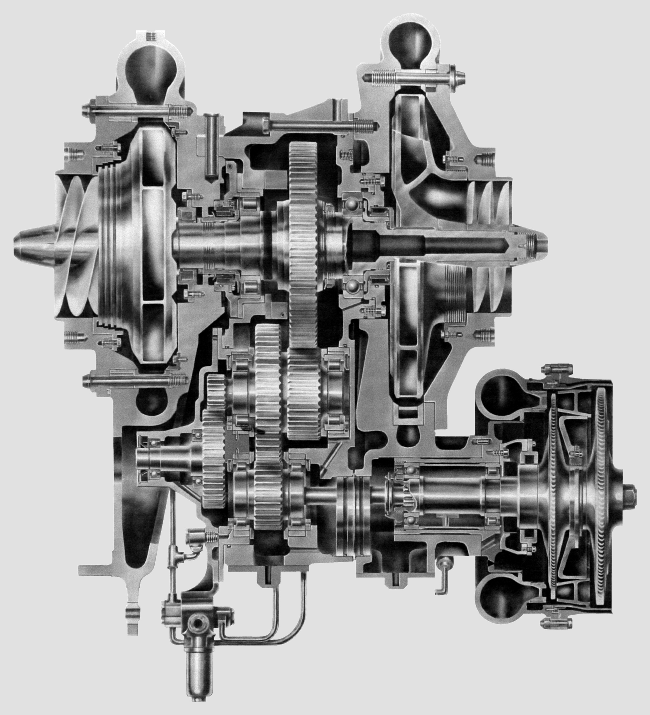
A so-called turbopump inducer has the function of raising the inlet head by an amount sufficient to prevent significant cavitation in the following pump stage. It is an axial impeller with a low number of vanes, which is arranged immediately upstream of the actual centrifugal pump impeller and rotates at the same rotational speed.
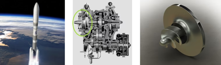
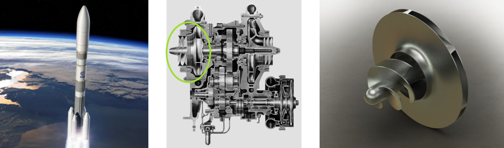
Turbopump of a space launcher [1]
With the aim of evaluating fluid-dynamic behavior, the need arises to build a system of geometric parameterization that allows to investigate the geometrical aspects that most influence the performance of a turbopump inducer, minimizing costs and times investment. From the use of the software CAESES, GeoPI (Geometric Parametrization of Inducer) was born, a fully automated project workflow, in which, using appropriate dedicated features, it is possible to build the complete geometry of the first component of the turbopump, including the generation of the fluid domain necessary for subsequent CFD analysis. The project encompasses a series of features that have been written in accordance with literature guidelines for the construction of geometries such as the turbopump inducer.
GeoPI: Geometric Parametrization of the Turbopump Inducer
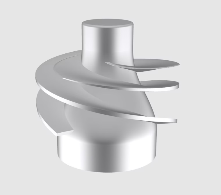
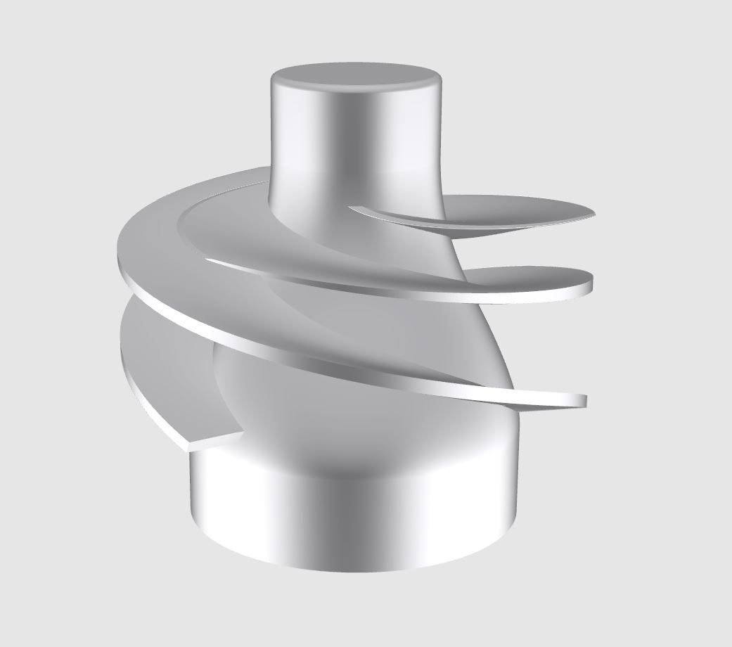
Turbopump inducer geometry
GeoPI is a project dedicated to the design of the inducer component. The first component of the turbopump has geometrical characteristics that allow it to operate even in very strong cavitation conditions, to ensure that the central core of the turbopump, i.e., the impeller, can work in the absence of vapor bubbles. The design of this component differs from the design of a classic impeller, as it has a particularly sharp leading edge shape and a leaning blade to ensure a small value of prevalence to the working fluid.
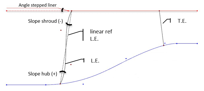
As a start, in the project, the geometry of the meridional channel is defined by inserting the hub and shroud contours through B‑spline curves with four or five control points, respectively. The definition of the meridional channel also includes the leading and trailing edge, that are positioned in % of the total length of the meridional curves. In particular, the shape of the leading edge can assume a curvilinear shape as a result of two angle values defined at the hub and shroud relative to the linear reference. To conclude this first part, it is possible to define the constant or non-constant curve that characterizes the blade’s tip clearance.
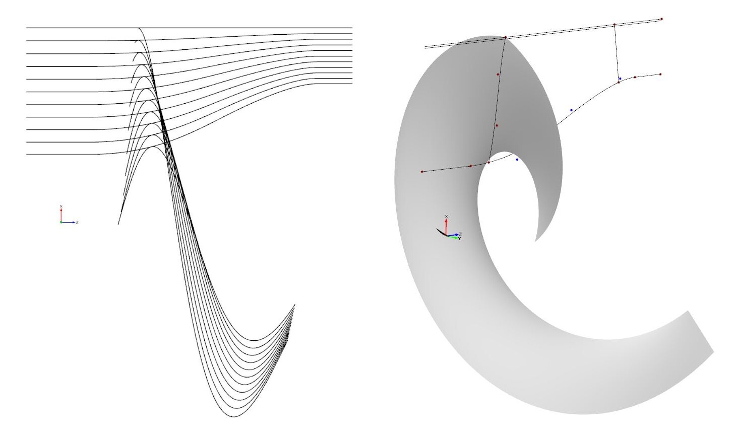
As mentioned above, the inducer has a characteristic shape that differentiates it from a classic impeller. In fact, in order to obtain its shape, it was necessary to implement various routines (features) through the scripting environment of CAESES. Starting from the knowledge of a blade angle (β) distribution at the shroud, a wrap angle (θ) value at the leading edge, and a distribution for the lean of the blade, this feature allows to obtain a desired number of camber curves such as to respect the value of Δθ imposed at the hub through linear interpolation in spanwise direction. For the characterization of the inducer shape, the user has therefore the possibility to define the flow angle distribution at the shroud and the distribution of the wrap angle shift at the hub from the leading to the trailing edge of the blade, both as B‑spline curves with three/four control points defined with respect to the M‑Prime (m’ – radius normalized meridional distance) coordinate. This step finally results in the camber surface, which is obtained as a lofted surface from the interpolation of n camber curves in spanwise direction, with respect to the inputs provided by the user.
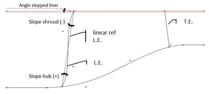
Meridional contours
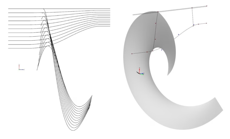
Camber curve interpolation in spanwise direction
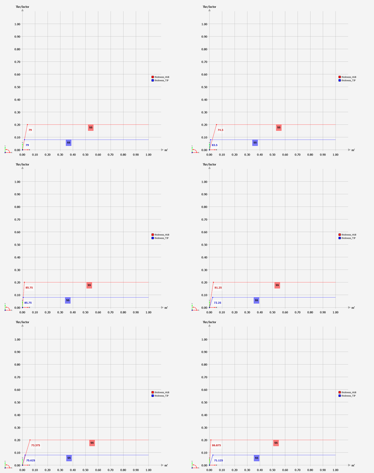
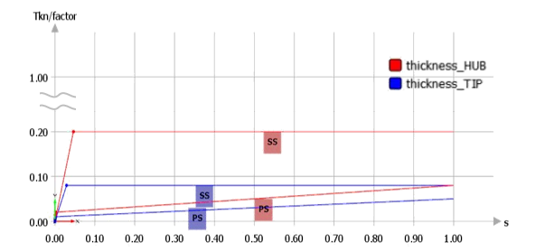
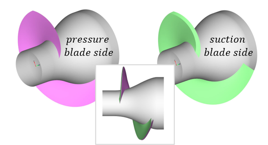
The next step is dedicated to the definition of the blade thickness. The thickness distributions for suction and pressure side of the blade can be varied fully independently. Furthermore, there is the possibility to specify different distributions for the hub and the tip location, thus allowing the definition of a completely free-form blade. Again, different features have been implemented to obtain a solid blade shape with a customized definition. Each thickness distribution is constructed by indicating the desired values for leading and trailing edge and an angle value for the shape of leading edge. The part of the distribution dedicated to the leading edge can be either linear or quadratic, in order to obtain the classic wedge shapes or more circular shapes, respectively. The thickness is applied normal to the camber surface defined in the first step, thus obtaining the final blade geometry.
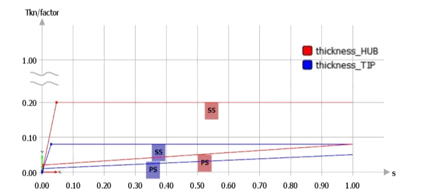
Thickness distributions
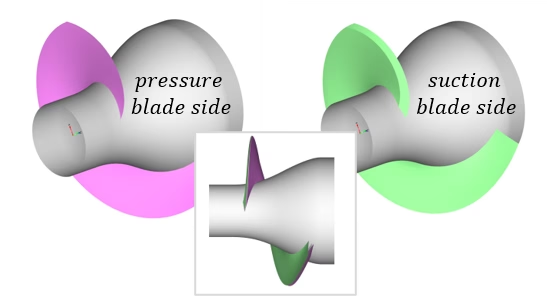
Surfaces of the blade sides
Once the blade is built, it is necessary to create the geometric environment for subsequent CFD analysis. In order to obtain a fluid domain that comprises a single blade, a custom routine was implemented to obtain periodicity surfaces. Through this feature, for each camber curve defined above, a similar curve is obtained with upstream and downstream extensions to meet the respective inlet and outlet surfaces. The periodicity surfaces should be as aligned as possible with the blade shape and respect the θ variation imposed between the hub and shroud sections. This concept allows to obtain an exact circular sector in the front part of the domain, avoiding any wedges between surfaces.
Inside the fluid domain, it is possible to insert upstream extensions to evaluate the impact of the nut introduction and downstream extensions to insert a channel shrinkage in order to obtain a more stable analysis convergence. The CFD domain is created with various BRep (Boundary Representation) operations, obtaining a watertight fluid domain with closed edges.
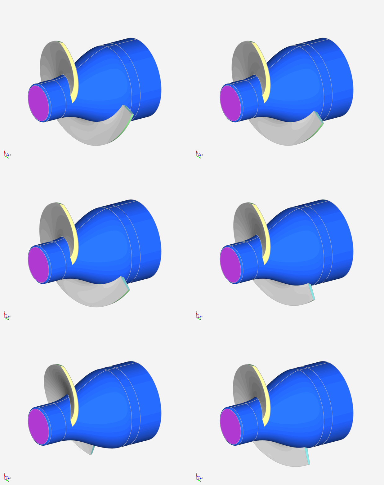
Through the variation of the parameters defined by the user it is possible to obtain very different blade shapes. Here are some examples obtained by varying meridional channel contours, the flow angle distribution, the wrap angle shift distribution, and the leading edge shape from hub to shroud section.
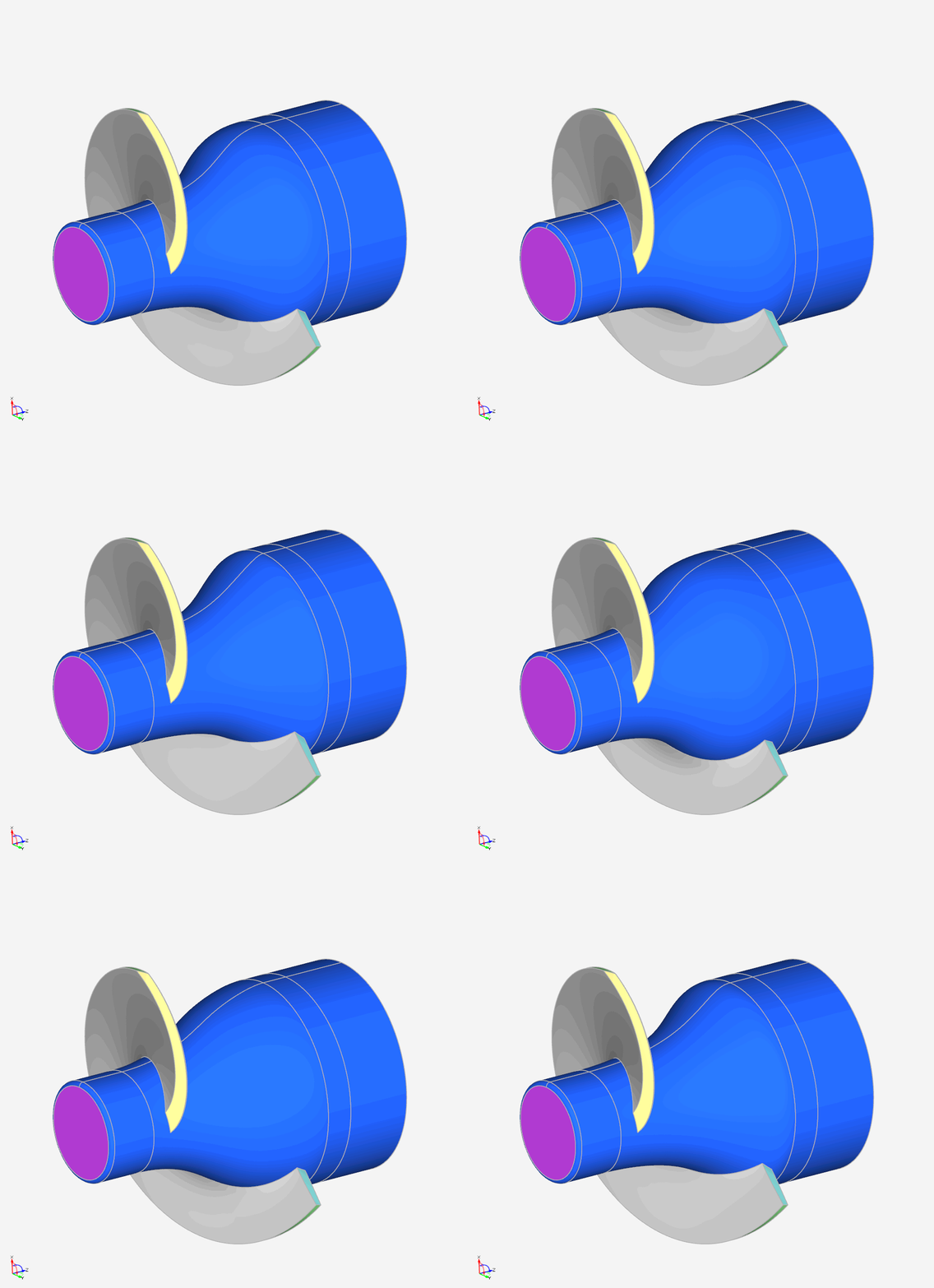
Meridional contour variation
β distribution at the shroud
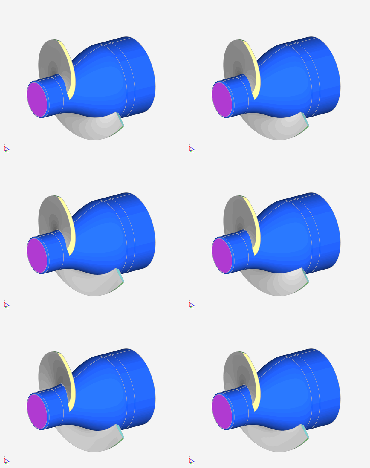
Δθ distribution
Leading edge shapes with different value of angles from hub to shroud
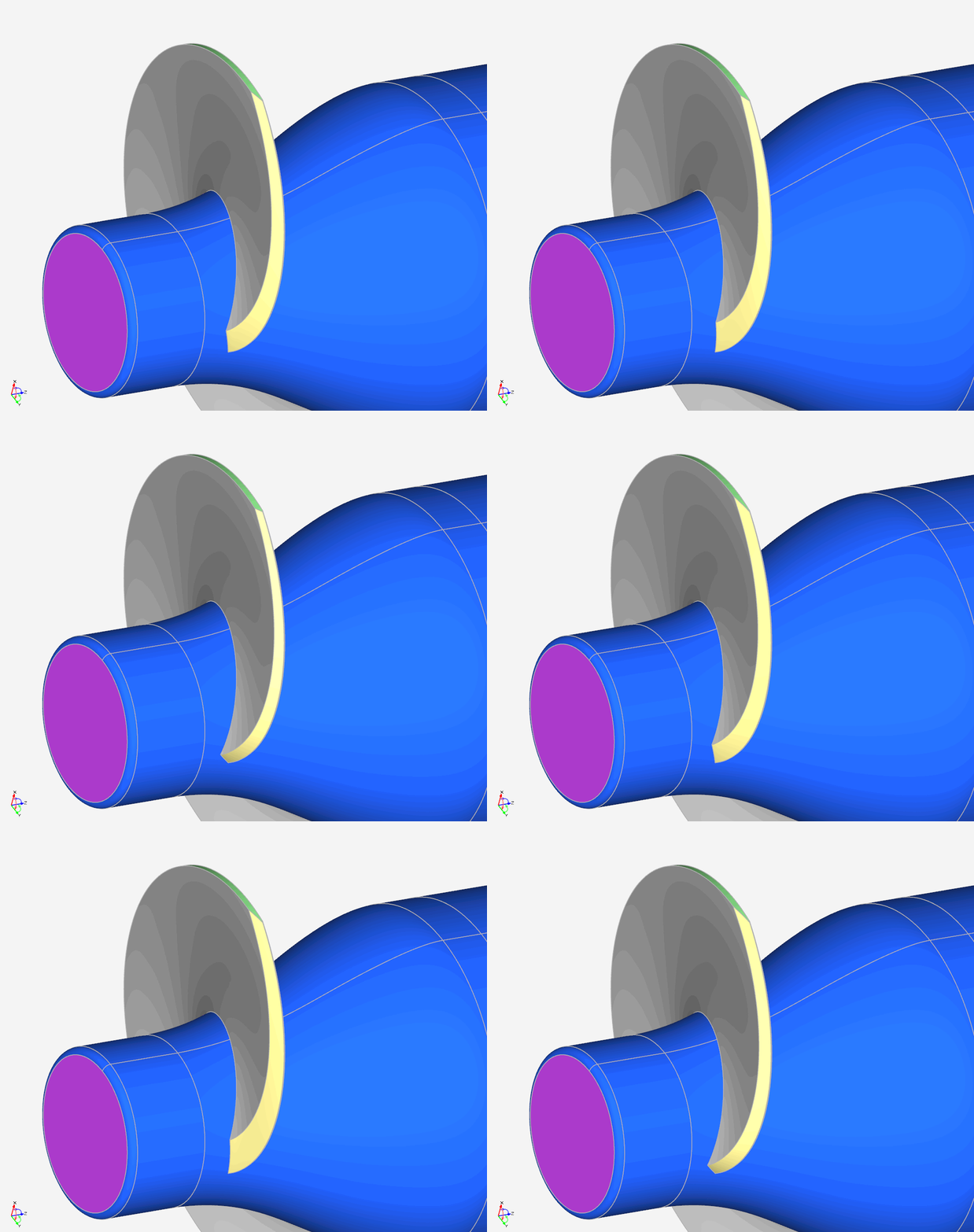
Leading edge shape variation
External Workflow with ANSYS CFX
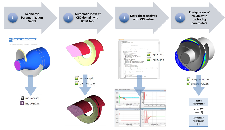
The fluid dynamic analysis was integrated in the CAESES design environment by coupling to various ANSYS software tools. Following the creation of the inducer geometry in CAESES, the CFD fluid domain is exported in TETIN format, whereby different colors are associated to each part of the geometry. This is useful for the meshing process in ICEM, which recreates the subdivision of geometry as set in CAESES and allows a repeatable assignment of settings such as boundary conditions or cell sizes to the different patches of the geometry. Through a series of scripts, the grid for computational analysis can be generated in a fully automated way for each variant. Even the calculation, directly in cavitating conditions, is built through an automated process. Each CFD analysis uses the double precision solver, the SST k‑ω model for turbulence closure, and the Rayleigh-Plesset model as cavitation model. Downstream of the entire process, each multi-phase calculation is post-processed using an in-house code written in Fortran. With this code, values of various objective functions are evaluated in accordance with the extension and the position of the cavitation bubble that develops within the studied inducer. At the end of the post-processing step, the value of a penalty function is obtained for assessing the quality of the created geometry.
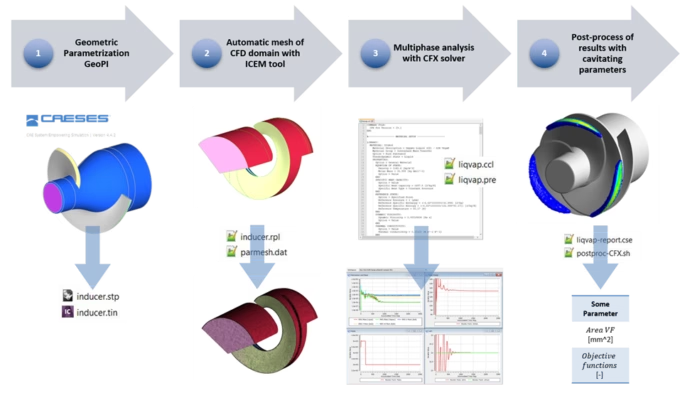
Workflow using CAESES and Ansys tools
Results for the Turbopump Inducer Geometry
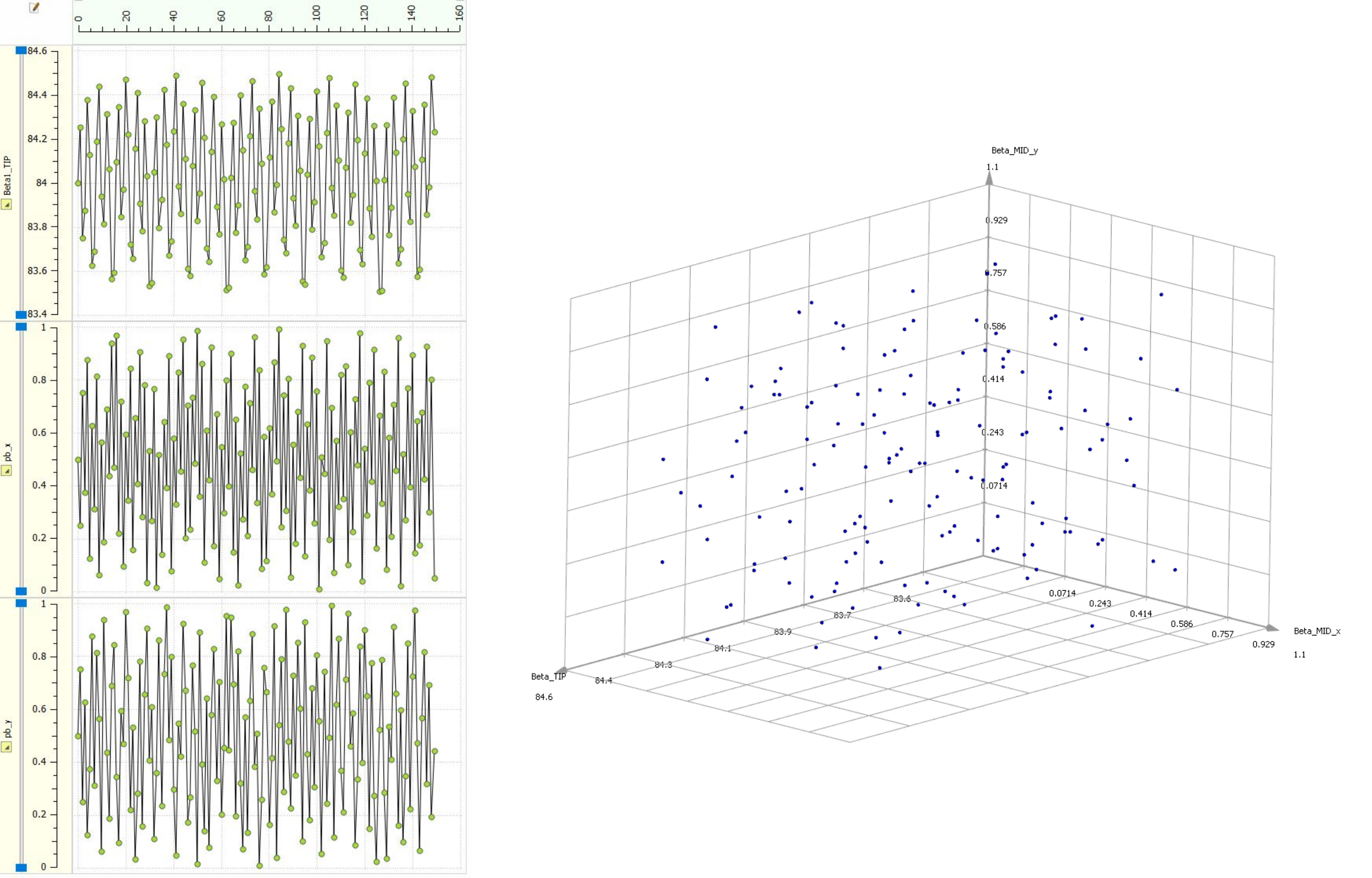
In order to obtain knowledge about the impact of various geometric parameters indicated in the previous sections, an initial sensitivity analysis was performed through a Sobol algorithm, creating a study with 150 inducer variants.
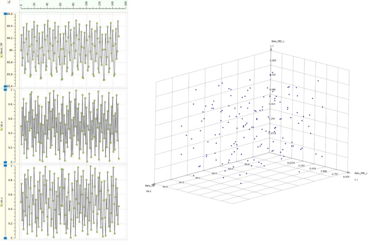
Variation charts of parameters dedicated to the distribution of the blade flow angle
It was decided to keep the contours of the meridional channel and the distribution of the blade wrap angle shift unchanged, while three parameters dedicated to the distribution of the blade flow angle at the shroud have been varied. Variations of about one degree in the leading edge value and a complete change in the [0:1] range of the central control point of the B‑spline curve were examined. The variability of the x,y‑coordinates of the central control point of the β distribution has led to substantially different geometries, obtaining very variable results in the cavitating condition.
The comparison with the initial geometry, through the outputs provided by the post-processing part, allowed to identify the best geometry among those tested. With only very small variations in the values of the parameters, an improvement of about 36% of the penalty function value in the development and spatial extension of the cavitation bubble has been obtained. Future work will be carried out with additional sensitivity studies on the distribution of the blade wrap angle shift and on the shape of the leading edge, as well as through the exploitation of distributions of varying thickness between the two blade sides.
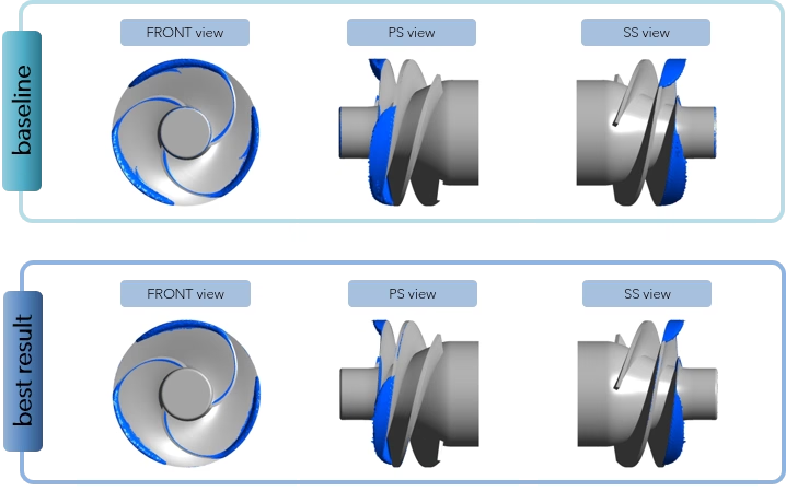
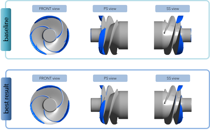
Comparison between original geometry and the best one obtained by the sensitivity analysis
About the Author
Many thanks to Erika Ghignoni from the University of Florence for sharing these fascinating research insights.
Erika Ghignoni received her master’s degree from the University of Florence in Industrial Engineering in 2017. She is currently working as a PhD student at the Department of Industrial Engineering in the research group dedicated to the study of internal and external aerodynamics. Her research work focuses on studying and predicting the performance of turbopumps for space applications. The focus is on the design of various components and, with particular attention, on the assessment of cavitation impact on their performance. The study is part of a collaboration with a company of world-wide importance in the aerospace field.

“Knowing and using the software CAESES has allowed me to speed up the analysis and evaluation times in my research project. CAESES is a parametric CAD software that allows you to easily combine the implementation part with high-level 3D graphics resolution in real time. Modern, high-performance and use-friendly, through the free scripting environment, the CAESES software has revolutionized the approach of an engineer to the design of each component, making the work to be performed more streamlined.”
Erika Ghignoni
PhD student at the University of Florence