Optimizing Tire Tread Patterns for Reduced Splashing
A case study with Particleworks® and CAESES®
The development of advanced automotive systems in recent years such as electrification, self-driving systems, and enhanced safety systems among others has led to a drastic increase in the number of electrical components such as sensors, radars, and cameras. Avoiding wetness of these components to avoid damage and corrosion, so that they function effectively and reliably, is of great interest. One useful approach is to mitigate splashing of the vehicle’s body and underbody, which is one of the main causes of water damage. This study describes a simulation-driven optimization process to investigate the influence of tire tread patterns on water splashing.
CFD Simulation Model
The model domain used in the simulation was a symmetry model of half the front section of the vehicle, or essentially a quarter model with a focus on the left front wheel and nearby surfaces. This was deemed to be a reasonable trade-off in terms of simulation speed and accuracy. Naturally, the simulation included the forward motion of the vehicle (set to 80 km/h), as well as the rotation of the wheel (65.4 rad/s), which then would scatter and splash the water distributed on the road surface.
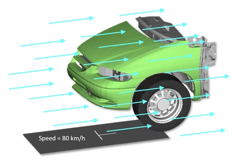
Splashing caused by the movement of a vehicle along a wet road is a challenging simulation problem. A meshless particle method based on MPS (Moving Particle Simulation) was used, which has the advantage that it can directly handle the dynamic motion of water droplets modeled as particles interacting with the surrounding environment. Also, being meshless, the method is well suited for detailed geometries with motions and multi-phase fluids, being typically faster and more efficient than conventional CFD solvers. The commercial CFD code Particleworks®, developed by Prometech, was used for the simulations. For more technical details about Particleworks® and the MPS method, you can visit their website or take a look at the paper upon which this study is based.
Parametric Tire Model
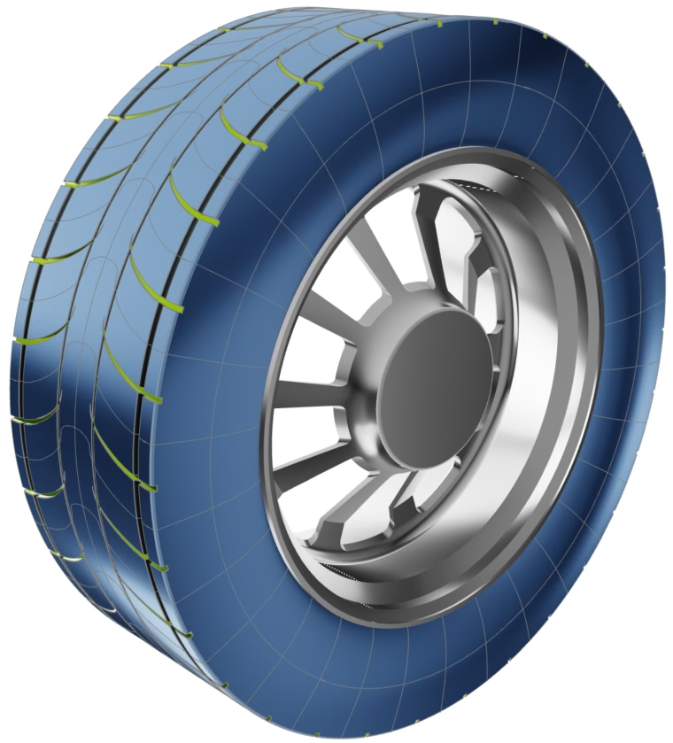
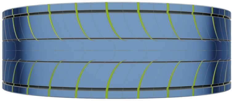
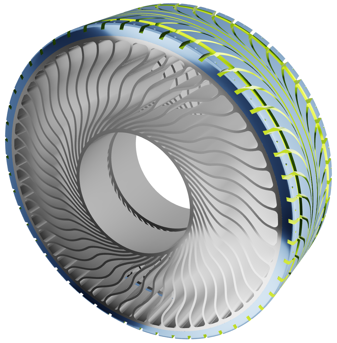
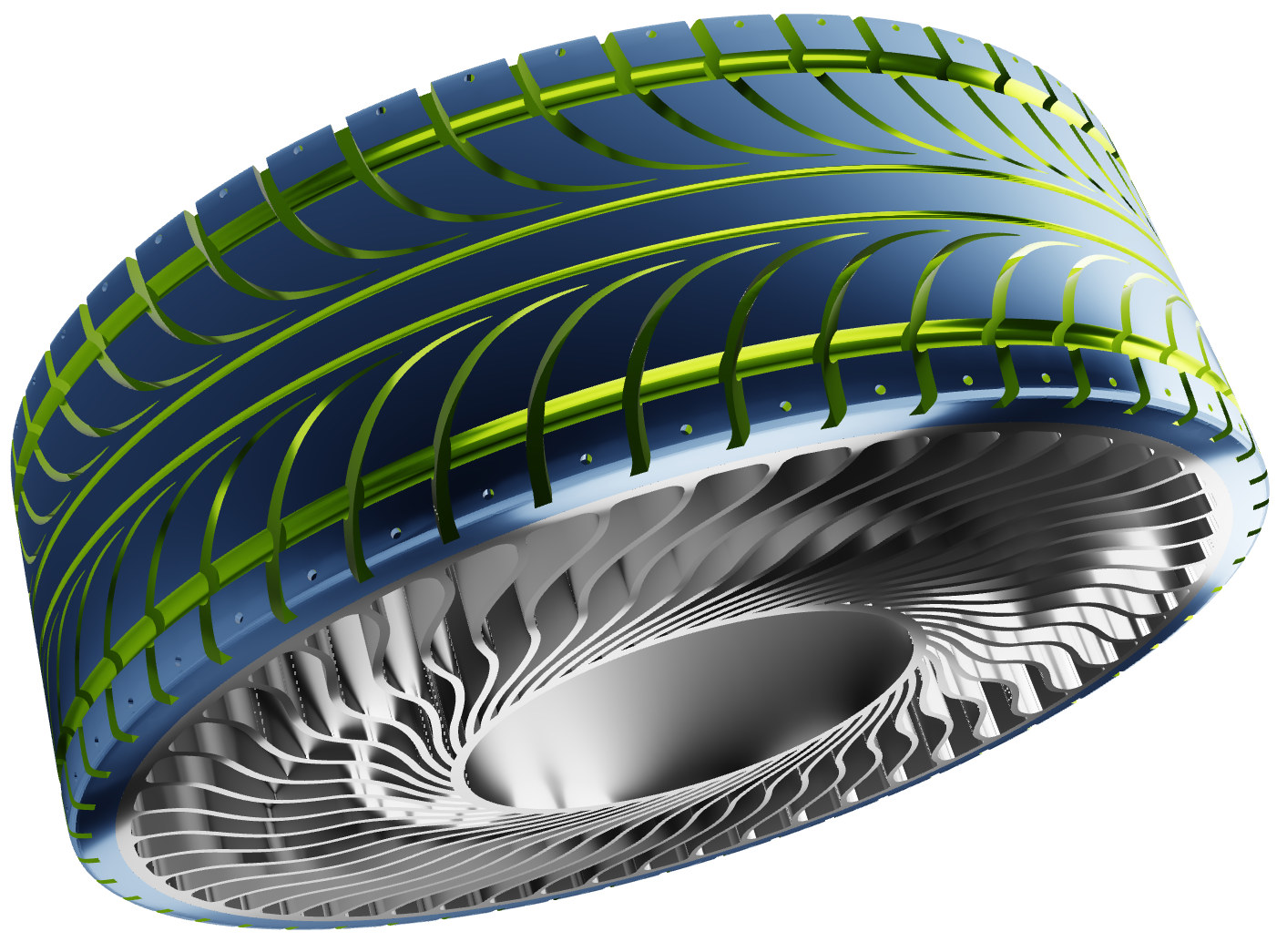
CAESES® was used to automatically generate the various designs of the tire and its tread patterns, based on changing the values of the parameters over a given range. Geometry variations of the various treads, grooves, dimples, sipes, etc. were made by adjusting the spacing, width, depth, and arrangements of the features. Even topological changes are possible, whereby the number of these features can change, which can be very powerful in an optimization study when coupled to a meshless CFD solver like Particleworks®. The images below show an example of a tire model built in CAESES® inspired by airless or non-pneumatic tires with their interesting spoke structures designed to support the weight of the vehicle and eliminating the possibility of ever having a flat tire.
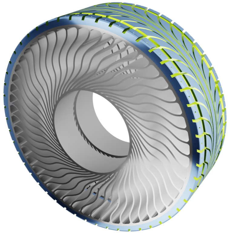
Parametric CAESES Model of the tire and its tread patterns in sideview
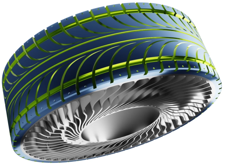
Parametric CAESES Model of the tire and its tread patterns
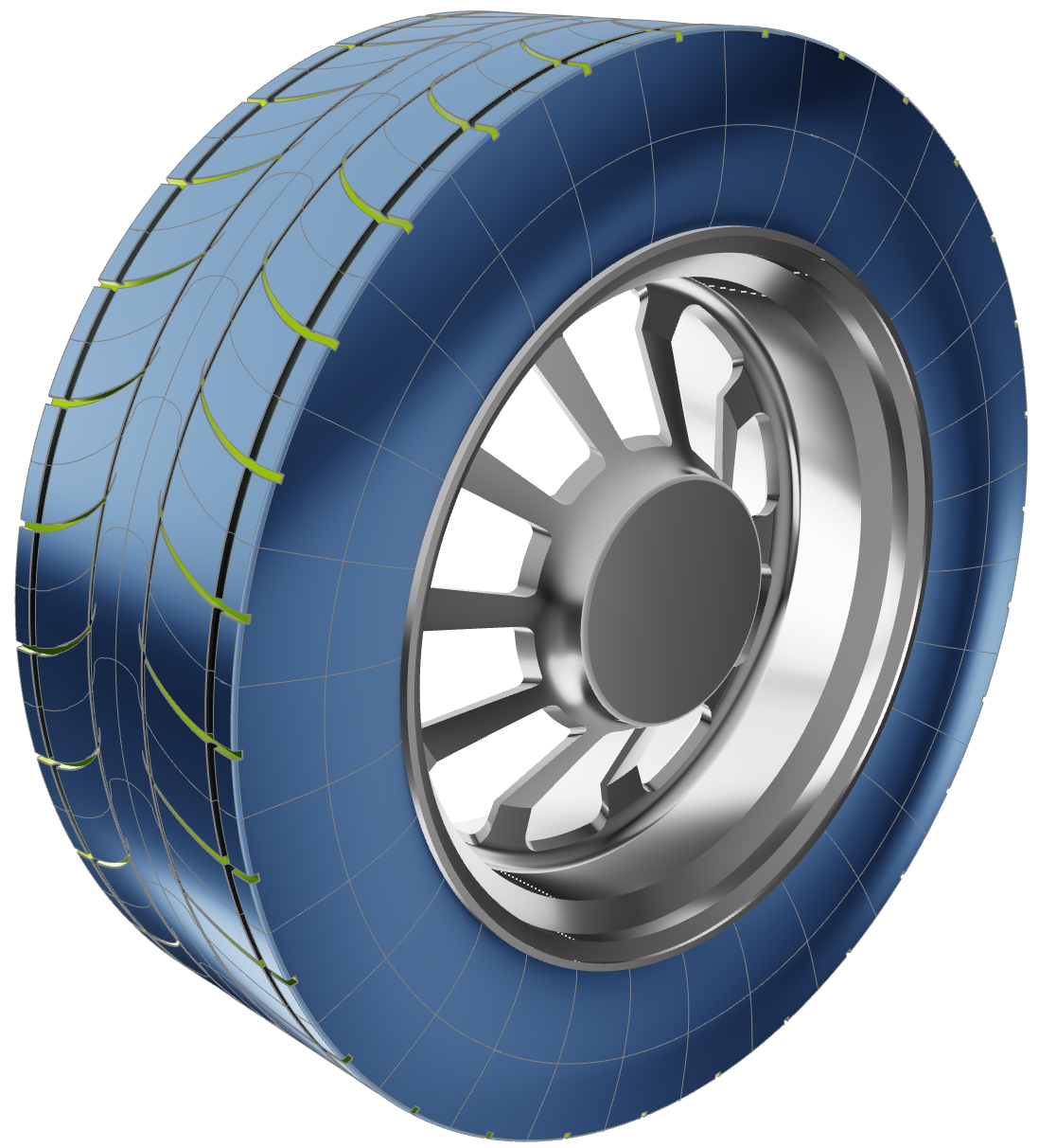
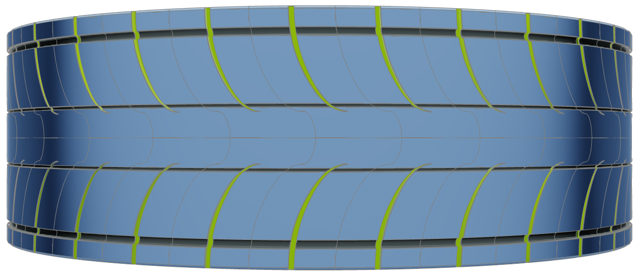
The present case study is a demonstrator project to show the method, toolchain, and workflow, and thus, a less complex conventional tire was studied in order to have faster computations. The tire tread model was described with 12 parameters related to the geometry of the treads and longitudinal grooves (inner and outer), including width, depth, tread length and curvature, number of treads, etc.
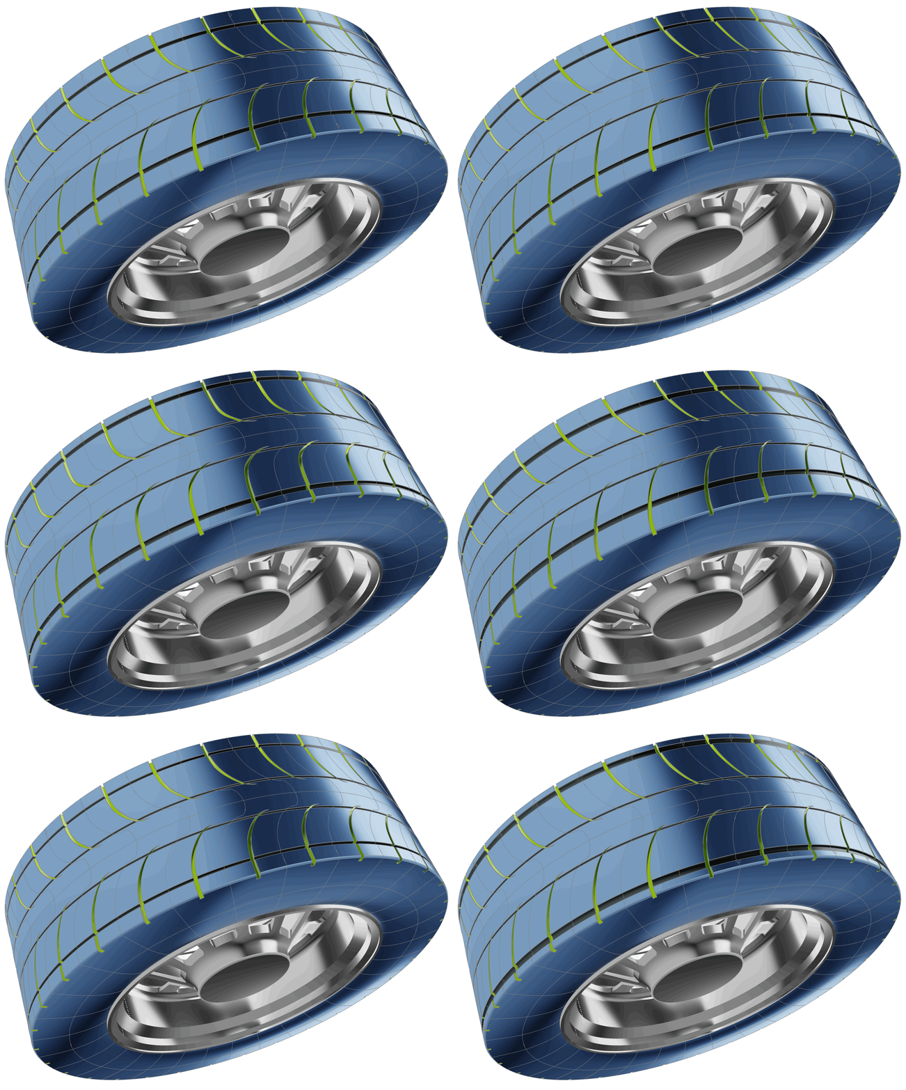
The following animation illustrates how design candidates can easily be generated by changing the values of select design variables. This image shows only the 4 variables that were changed in the 2nd stage of the optimization (see below).
Automation Workflow and Optimization Strategy
In addition to CAD capabilities, CAESES® is also a process integration and design optimization (PIDO) platform. It generates the design variants by changing the parameters within the set range of upper and lower bounds, while respecting any defined geometric constraints. Then, the model is exported and passed to Particleworks® to conduct the simulations.
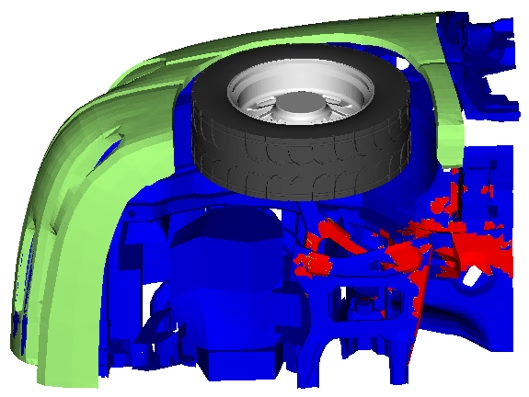
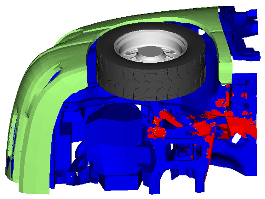
The objective function was specified as the area subject to water splashing, which was to be minimized. These result values from the simulation were passed back to CAESES® and the optimization algorithms used them to rank each design and to further adjust the geometric parameters to create new designs with the aim of converging on the one with the best performance. The following figure shows an example of the underbody surfaces that became wet due to splashing, shown in red.
In the first optimization step, a DoE (design of experiments) study was run on 50 cases using the built-in Sobol algorithm, which is a quasi-random sampling method of the design space. The result of this initial sweep indicated that 4 of the 12 parameters had a larger influence on the objective function. Therefore, only these 4 parameters were further varied in the second optimization step. The specific parameters were related to the width and depth of the outer groove, as well as the curvature of the treads.
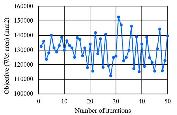
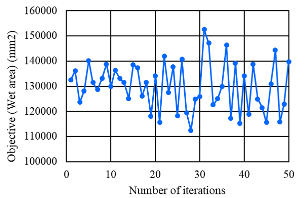
In the second step, a Response Surface optimization approach was applied to create a surrogate model. A Radial Basis Function network was adopted to approximate the response surface. First, the initial response surface was generated using 20 sampling points (4 design variables x 5). A Latin Hypercube Sampling was applied to generate additional sampling points. After that, the response surface was iteratively updated by adding sampling points based on selected variants along the Pareto frontier. Finally, a total of 50 computations were performed. On this surrogate model, the Multi-Objective Genetic Algorithm (MOGA) was used to search for the optimal solution in each iteration. The history of the objective function is shown in the graph below. This figure shows a large variation of the objective function for each iteration, and thus it appears that the design space had many local optima. Based on this study, the 28th iteration showed the best results, which was thus considered to represent the “optimum” tire tread arrangement.
Results and Conclusions
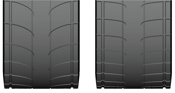
The result of the optimization study was that the total wetted area from the tire splashing was reduced by 14.1%, relative to the baseline case (130,953 mm² vs. 112,469 mm²). This was achieved since the optimized tire tread pattern managed to deflect some of the water towards the side and the rear of the tire. The comparison of tread geometries between baseline and best case are shown below, along with the figures showing the CFD results of the splashing patterns.
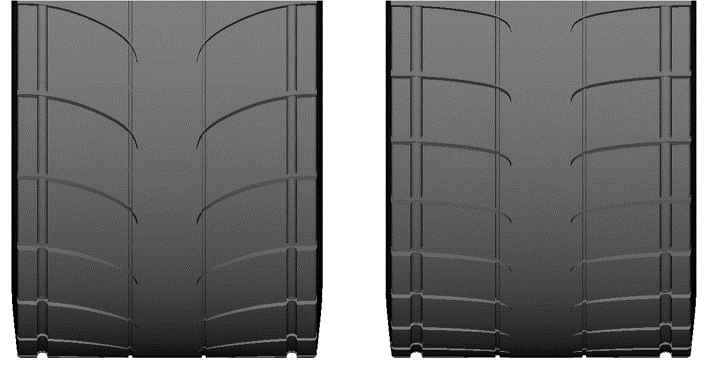
Baseline (left) and optimized tread pattern (right)
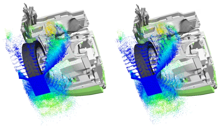
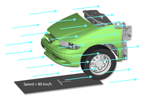
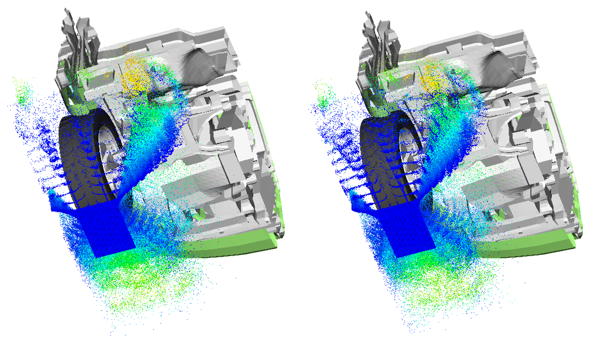
CFD results of the splashing patterns for baseline (left) and best design (right)
This demonstrator study has illustrated how CAESES®, coupled to Particleworks® in an automated workflow, was very effective at exploring a large number of design candidates and for conducting an optimization in order to significantly improve the tire tread design in terms of reducing water splashing characteristics on the underside of the vehicle. The MPS method employed by Particleworks® was ideally suited for simulating the challenging physics of splashing caused by the motion of a vehicle traveling along a wet road.
We would like to acknowledge and thank Dr. Sunao Tokura from Prometech Software Inc., Japan, the developers of Particleworks®. This case study is based on a presentation given at the NAFEMS World Congress 2021 entitled “Shape Optimization of Tire Tread Pattern to Minimize Water Splashing on Vehicle Body Using Particle Method CFD Simulation”.